
Movable germinator

A germination box and malt technology, which is applied in the preparation of malt, beer brewing, biochemical equipment and methods, etc., can solve the problems of difficulty in discharging, long discharging journey, and waste of malt, so as to avoid difficulty in discharging and ensure Connection strength, effect of reducing manufacturing cost

Inactive Publication Date: 2014-12-10
YANGZHOU XIANYE GRP
View PDF0 Cites 0 Cited by
  • Summary
  • Abstract
  • Description
  • Claims
  • Application Information

AI Technical Summary

Problems solved by technology

[0003] The above-mentioned structural features have the following defects: 1) The fixed structure of the sieve plate requires a spreading machine to lay the malt, which makes it difficult to lay the malt evenly, which affects the quality of germination. At the same time, the setting of the spreading machine also increases the occupancy of the germination box The space increases the production cost of the enterprise, and the sieve plate bears static load all the time, which puts forward higher requirements for the strength of the sieve plate;
[0004] 2) After the traditional structure is germinated, the malt needs to be discharged. It adopts the method of unloading machine to move back and forth, because the discharge port is generally only set on one side of the box, so the malt that is far away from the discharge port is discharged. The material travel is far away, so it is more difficult to make it completely discharged, resulting in waste of malt;
[0005] 3) Due to the defect in 2), it is necessary to clean the sieve plate. Some of the existing methods are manually cleaned, which is time-consuming and laborious, and the cleaning effect is poor; or the backwashing method is used, but its The cleaning effect is still not ideal;
[0006] 4) The traditional structure is affected by the strength of the sieve plate, and its specification setting is subject to certain restrictions, which affects the output of the germination box

Method used


Image

  • Movable germinator
  • Movable germinator

Examples


Embodiment Construction

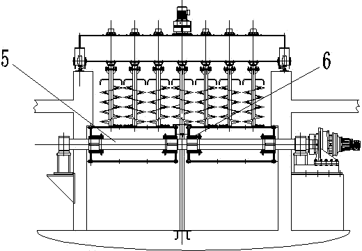
[0024] Germination feeding action of the present invention: open the moving conveyor belt 4, the malt flows into the feeding device through the feeding port 2, and the feeding device is equipped with a screw auger 7, which can evenly distribute the malt on both sides until the inner width of the germination box , The malt passes through the feed gate 8 device, which unifies the height of the feed and ensures the uniform ventilation and germination quality of the malt entering the box. After the whole germination box was covered with malt, the moving conveyer belt 4 stopped rotating, and the whole cloth action was completed.

[0025] During the germination period, it is necessary to adjust the fresh air louvers and exhaust louvers for ventilation, cooling in summer and heating in winter. Turn the wheat to replenish water to ensure the effective growth of malt.

[0026] Germination discharge action: after the germination cycle is over, the discharge action: first move the push ...


PUM


Abstract

The invention relates to a movable germinator which comprises a bed body (1), wherein a feed opening (2) is formed in one side of the bed body (1); a discharge opening (3) is formed in the other side of the bed body; a movable conveying belt (4) between the feed opening (2) and the discharge opening (3) is arranged in the bend body (1). According to the movable germinator, a traditional fixed screen plate is replaced by the movable conveying belt, material is conveyed very conveniently owing to the arrangement of the movable conveying belt, a spreading machine is not needed to be arranged, the material is fed only through the feed opening, and uniform distribution of malt is realizedautomatically with the moving of the movable conveying belt, so that the structure is more compact. The movable conveying belt of the movable germinator can move the material step by step to the discharge opening so as to automatically discharge the material without the need of a discharge machine; and all parts of the movable conveying belt discharge material at the discharge opening, thus avoiding the defect that material is difficult to discharge by the traditional fixed screen plate.

Description

technical field [0001] The invention relates to a mobile germination box, which belongs to the technical field of malt machinery and equipment. Background technique [0002] In the brewing industry, it is necessary to germinate malt. The existing germination box generally transports the material to a fixed sieve plate through the feed port, and then spreads the malt evenly on the sieve plate through a material spreading machine, and then ventilates and carries out The temperature and humidity are controlled and the germination is carried out by stirring. After the germination is completed, the malt is discharged by moving back and forth through the unloader, and then the sieve plate is cleaned to complete the germination process. [0003] The above-mentioned structural features have the following defects: 1) The fixed structure of the sieve plate requires a spreading machine to lay the malt, which makes it difficult to lay the malt evenly, which affects the quality of germin...

Claims


Application Information

Patent Timeline
IPC IPC(8): C12C1/033
Inventor 王琪张建峰
Owner YANGZHOU XIANYE GRP
Learn More