A method and device for electro-magnetic compound field cooperative laser cladding
A technology of laser cladding and magnetic field generating device, which is applied in the field of laser manufacturing, can solve the problems of limited control ability, single control form of laser cladding process, and difficulty in realizing layered or gradient control, so as to improve the force and efficiency, The effect of flexible regulation
- Summary
- Abstract
- Description
- Claims
- Application Information
AI Technical Summary
Problems solved by technology
Method used
Image
Examples
Embodiment 1
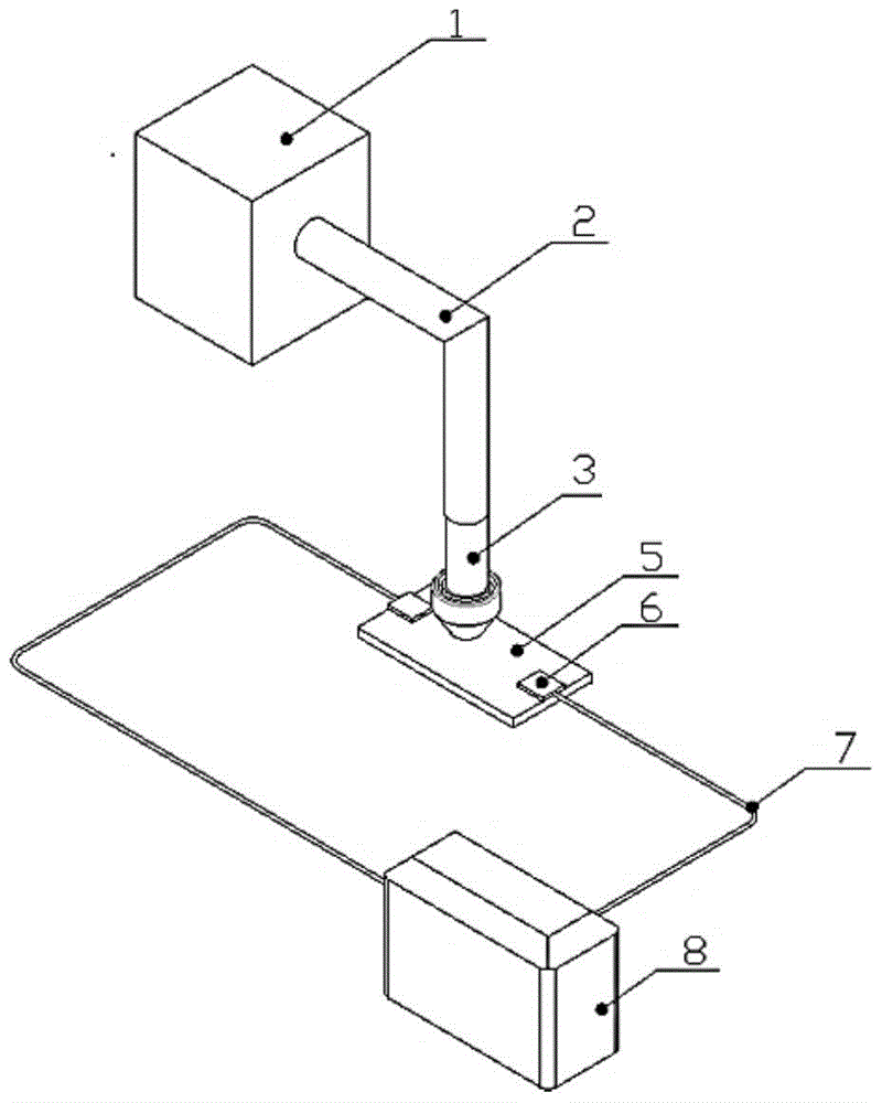
[0034] Such as figure 1 The device shown is an electric-magnetic compound field cooperative laser cladding device that uses an excitation device to provide a vertical steady-state magnetic field, including a laser, a laser transmission channel, a powder feeding head, an excitation device, a workpiece holder, a wire, a low-voltage large Current power supply, wherein the laser 1 and the laser transmission channel 2 can be connected through a flexible optical fiber or a flying optical path, the powder feeding head 3, the laser transmission channel 2 and the excitation device are coaxially coordinated, and the workpiece holder 6 is arranged on the workpiece (to be clad On both sides of the substrate) 5, the workpiece holder 6 is connected to a low-voltage high-current power supply 8 through a wire 7.
[0035] The electric-magnetic compound field cooperative laser cladding method adopted by the above-mentioned device includes the following steps:
[0036] (1) The surface of the su...
Embodiment 2
[0042] In this example, the magnetic field and electric field added in Example 1 are removed, and other process parameters remain the same. The solidification structure of the surface layer of the cladding layer obtained in this embodiment is as follows: Figure 4 shown. In comparative example 1 image 3 It can be seen that under the synergistic effect of the electric-magnetic compound field, the fluid in the molten pool is driven by the directional and stable Lorentz force, which changes the original flow field distribution in the molten pool of the cladding layer, and makes the growth direction of equiaxed crystals tend to Among them, the dendrites on the upflow side grow faster, and the dendrites on the backflow side grow slower, and the surface structure of the cladding layer observed in Example 2 without an electric-magnetic compound field is non-directional equiaxed crystal. Combining Example 1 and Example 2, it is proved that the synergistic effect of the electric-ma...
Embodiment 3
[0044] Such as figure 2 The electro-magnetic compound field cooperative laser cladding device using permanent magnets to provide a horizontal steady-state magnetic field, including lasers, laser transmission channels, powder feeding heads, permanent magnets, workpiece holders, wires, low-voltage high-current power supplies, among which The laser 1 and the laser transmission channel 2 can be connected through a flexible optical fiber or a flying optical path, the powder feeding head 3 and the laser transmission channel 2 are coaxially matched, the permanent magnets 9 are arranged on both sides of the workpiece (substrate to be clad) 5, and the workpiece holder 6 Arranged at both ends of the workpiece 5 , the workpiece holder 6 is connected to a low-voltage high-current power supply 8 through a wire 7 .
[0045] The electric-magnetic compound field cooperative laser cladding method adopted by the above-mentioned device includes the following steps:
[0046] (1) The surface of ...
PUM
| Property | Measurement | Unit |
|---|---|---|
| height | aaaaa | aaaaa |
Abstract
Description
Claims
Application Information
 - R&D
- Intellectual Property
- Life Sciences
- Materials
- Tech Scout
- Unparalleled Data Quality
- Higher Quality Content
- 60% Fewer Hallucinations
Browse by: Latest US Patents, China's latest patents, Technical Efficacy Thesaurus, Application Domain, Technology Topic, Popular Technical Reports.
© 2025 PatSnap. All rights reserved.Legal|Privacy policy|Modern Slavery Act Transparency Statement|Sitemap|About US| Contact US: help@patsnap.com


