
Fiber Cutter

A technology of fiber cutting machine and cutting mechanism, which is applied in the field of short fiber manufacturing, can solve the problems of cutting filament bundles into short fibers, reducing short fiber production efficiency, time-consuming and labor-intensive problems, and achieves high cutting precision, simple structure and convenient manufacture. Effect

Inactive Publication Date: 2016-08-17
DONGGUAN TANSUO COMPOSITE MATERIAL
View PDF5 Cites 6 Cited by
  • Summary
  • Abstract
  • Description
  • Claims
  • Application Information

AI Technical Summary

Problems solved by technology

[0002] Short fiber, also known as cut fiber, the cutting process is the last process in the short fiber production process. It is the short fiber cut into the long filament bundle by a cutting machine. However, the existing cutting machine is cutting the long filament bundle Sometimes, the filament bundle between the wire wheel and the cutter head will loosen, which will cause the cutter head on the cutting machine to fail to cut the filament bundle into short fibers well. If the cutter head on the cutting machine is to be smooth To cut filament bundles, it is necessary to turn off the starting power of the cutting machine first, and then manually tighten the filament bundles between the wire wheel and the cutter head, so that the filament bundles can be suitable for cutting filament bundles by the cutter head. tension, which is not only very time-consuming and labor-intensive, but also greatly reduces the production efficiency of short fibers

Method used


Image

  • Fiber Cutter
  • Fiber Cutter
  • Fiber Cutter

Examples


Embodiment Construction

[0040] The technical solutions of the present invention will be further described below in conjunction with the accompanying drawings and through specific implementation methods.

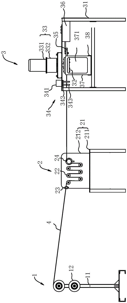
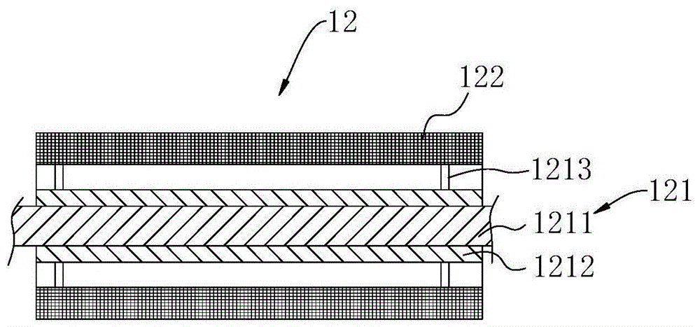
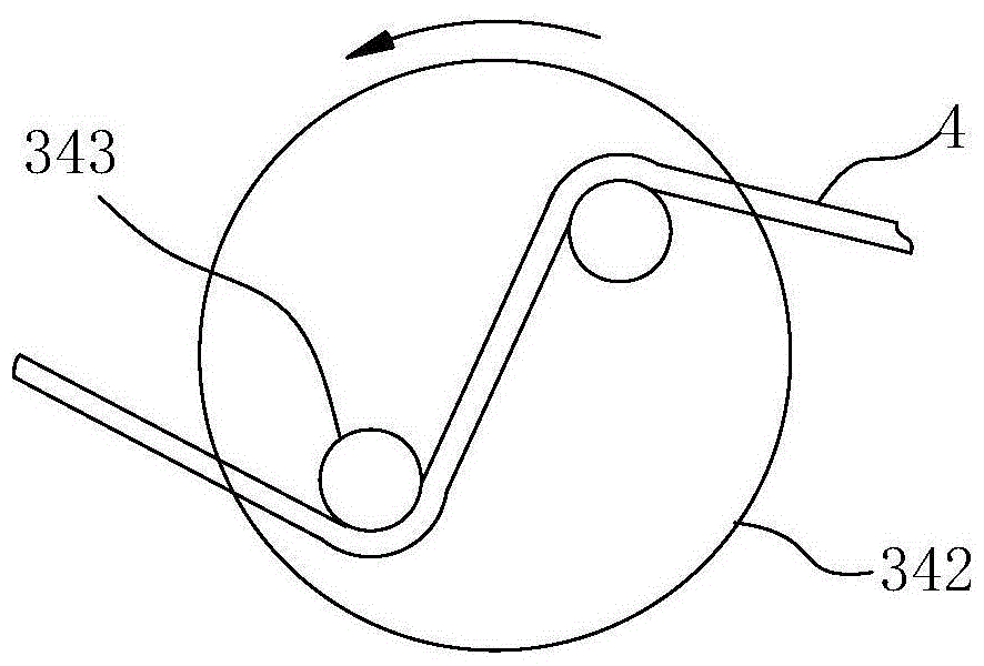
[0041] Such as figure 1As shown, a fiber cutting machine described in this embodiment includes a wire wheel mechanism 1, a cutting mechanism 3 and a tensioning mechanism 2 between the wire wheel mechanism 1 and the cutting mechanism 3. The wire wheel mechanism 1 includes a wire wheel fixed Frame 11 and at least one wire wheel part 12 fixed on the fixed frame 11, the wire wheel part 12 includes a wire wheel 121, and the outside of the wire wheel 121 is sleeved with a tow cover 122 composed of long tows 4 to be cut, and the cutting mechanism 3 includes a frame 31, a cutterhead 32 for cutting the filament bundle 4 into short fibers, a first power unit 33 for driving the cutterhead 32 to rotate, and a press for pressing the filament bundle 4 on the cutterhead 32. Wheel 35 and the tension adjusting devi...


PUM


Abstract

The invention discloses a fiber cutting machine, which comprises a wire wheel mechanism, a cutting mechanism and a tensioning mechanism located between the wire wheel mechanism and the cutting mechanism. The wire wheel mechanism includes a wire wheel fixing frame and at least one wire fixed on the wire wheel fixing frame. The wheel part, the wire wheel part includes a wire wheel, and the outer side of the wire wheel is covered with a tow sleeve composed of long filament bundles to be cut. The cutting mechanism includes a frame, a cutter head, a first power device for driving the cutter head to rotate, The pressure wheel that can press the filament bundle on the cutter head and the tension adjustment device for adjusting the tension of the filament bundle. The power unit, the pressure roller and the tension adjustment device are all fixed on the frame. The force adjustment device is located on the side of the cutter head close to the wire wheel mechanism, the pressure wheel is located on the side of the cutter head away from the wire wheel mechanism, and the output shaft of the power device is connected to the cutter head; the tensioning mechanism includes a tensioning wheel fixing frame, a tensioning wheel The fixed frame is provided with at least one tensioning wheel for tensioning the filament bundle. The invention can make the tension force of cutterhead cutting when the filament bundle is produced.

Description

technical field [0001] The invention relates to the field of short fiber production, in particular to a fiber cutting machine for cutting long filament bundles into short fibers. Background technique [0002] Short fiber, also known as cut fiber, the cutting process is the last process in the production process of short fiber. It is the short fiber cut into the long fiber bundle by the cutting machine. However, the existing cutting machine is cutting the long fiber bundle Sometimes, the filament bundle between the wire wheel and the cutter head may loosen, which will cause the cutter head on the cutting machine to fail to cut the filament bundle into short fibers well. If the cutter head on the cutting machine is to be smooth To cut filament bundles, it is necessary to turn off the starting power of the cutting machine first, and then manually tighten the filament bundles between the wire wheel and the cutter head, so that the filament bundles can be suitable for the cutter ...

Claims


Application Information

Patent Timeline
Patent Type & Authority Patents(China)
IPC IPC(8): D01G1/04
Inventor 杨建恒李书清尹涛胡艳民
Owner DONGGUAN TANSUO COMPOSITE MATERIAL
Learn More