Pipe foundation pit predeformation support method

A pre-deformation and foundation pit technology, which is applied in excavation, infrastructure engineering, construction, etc., can solve the problem of the construction party's weak technology and awareness of welding, installation, protection, etc., high requirements for supporting structure construction technology, and long foundation pit construction time. and other problems to achieve the effect of preventing the installation of pipe joints, reducing deformation resistance requirements, and reducing active earth pressure

Inactive Publication Date: 2014-12-10
HENAN UNIVERSITY
View PDF5 Cites 7 Cited by
  • Summary
  • Abstract
  • Description
  • Claims
  • Application Information

AI Technical Summary

Problems solved by technology

[0006] There are also problems in this method: 1. The construction process is complicated. The small deformation foundation pit project requires relatively high construction technology and many links for the support structure, and the support structure cannot be reused. Although the support structure belongs to temporary, However, it is permanently buried around the building, causing environmental pollution or affecting the construction of adjacent buildings.
Therefore, the construction time of the foundation pit is long, and the time and space for the deformation of the rock and soil mass and the supporting structure are given. The process content is complicated, and it is not suitable for rapid foundation pit engineering.
2. Monitoring is e

Method used


Image

  • Pipe foundation pit predeformation support method
  • Pipe foundation pit predeformation support method
  • Pipe foundation pit predeformation support method

Examples


Embodiment

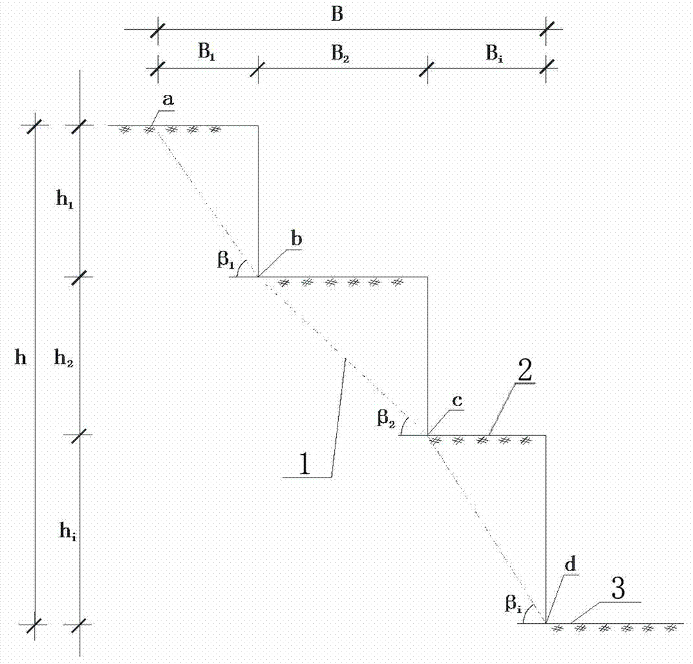
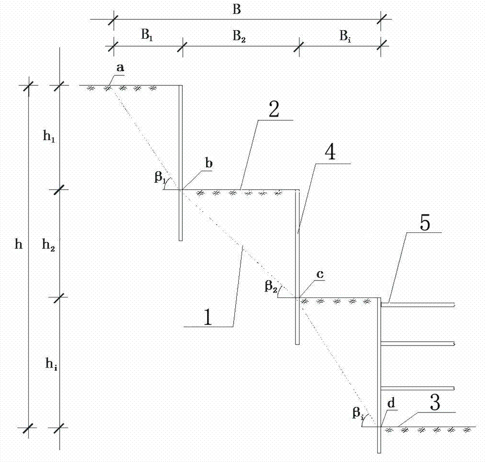
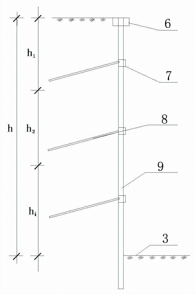
[0028] Example: see Figure 1-Figure 3 , 1-sliding surface of foundation pit, 2-step, 3-bottom of foundation pit, 4-supporting pile, 5-supporting rod, 6-crown beam, 7-waist beam, 8-anchor cable, 9-supporting column .

[0029] The pre-deformation support method for pipeline foundation pit includes the following steps:

[0030] A. Divide several steps 2 above the final step 2, remove the soil on the step surface, reduce the active earth pressure on the sliding surface of the soil and allow the sliding of the soil on the sliding surface;

[0031]B. Install steel sheet piles or cavity piles on the facade of each step 2, the force of the upper step 2 is not transmitted to the lower step 2, and the steel sheet pile or cavity pile bears the active earth pressure or sliding soil in the step 2 The maximum value of the sliding force, and its deformation meets the requirements of supporting structure materials and integrity;


PUM


Abstract

The invention discloses a pipe foundation pit predeformation support method. The method comprises the following steps: (A) a part above a final step is divided into multiple steps; and soil bodies on the step surfaces are removed, so that the active soil pressure on the sliding surfaces of the soil bodies is reduced, and the sliding of the soil bodies on the sliding surfaces is allowed; (B) steel plate piles or cavity piles are arranged on the vertical surfaces of all the steps; the acting force of the previous steps is not transferred to the later steps; the steel plate piles or the cavity piles bear the biggest value of the active soil pressure in the steps or the sliding force in the sliding soil bodies; and the deformation of the steel plate piles or the cavity piles satisfies the material and integrity requirements of a support structure; and (C) measuring points are preset on all the steel plate piles or the cavity piles, and are directly measured; the parts with the deformation exceeding a normal limit state are reinforced; and the generation of unstable state is controlled timely. The method allows the soil bodies on all the steps above the final step to generate large deformation, even the deformation exceeding dozens of centimeters, so that the construction process is simple, the procedures are easily realized, and the construction cost is far lower than that of the foundation pit support design controlled according to small deformation.

Description

[0001] Technical field: [0002] The invention relates to a pipeline foundation pit support technology, in particular to a pipeline foundation pit pre-deformation support method. Background technique: [0003] Foundation pit support is a temporary project for the construction of buildings below the ground. Its basic function is to ensure the short-term operation safety of the foundation pit, and the surrounding buildings (or structures) of the foundation pit will not be affected or although they are affected, the surrounding buildings will be affected. It has no effect on the function and use of the foundation pit, that is, the deformation generated after the excavation of the foundation pit is within the range of the anti-deformation value of the existing building. [0004] The difference between oil and natural gas pipeline foundation pit engineering and building foundation pit engineering is that in most cases, it is located in an open area without buildings-fields, river...

Claims


Application Information

Patent Timeline
IPC IPC(8): E02D17/04
Inventor 吴保全李国良张云福郭振军王擎张吉坤李军海彭武刘卓吴歌刘凤利
Owner HENAN UNIVERSITY
Why Eureka
Try Eureka