A cold storage delivery door structure
What is Al technical title?
Al technical title is built by PatSnap Al team. It summarizes the technical point description of the patent document.
A cold storage and door panel technology, applied in door/window fittings, building structures, power control mechanisms, etc., can solve the problems of easy waiting for goods outside the door, low work efficiency, accumulation, etc., to avoid a large number of leakage and save switches time, the effect of increased efficiency
Active Publication Date: 2018-08-28
JINGKELUN REFRIGERATION EQUIP CO LTD
View PDF3 Cites 0 Cited by
Summary
Abstract
Description
Claims
Application Information
AI Technical Summary
This helps you quickly interpret patents by identifying the three key elements:
Problems solved by technology
Method used
Benefits of technology
Problems solved by technology
The use of ordinary sliding doors is easy to cause heat exchange with the outside world when opening and closing, resulting in leakage of cold storage in the cold storage; and there is no automatic function
The use of ordinary automatic shutter doors is not only costly, but also takes a long time to roll up and down the shutter, causing goods to easily wait outside the door, resulting in accumulation, resulting in low work efficiency, and because the process of rolling up and down the shutter takes a long time, it will also cause cold storage. A large amount of cold energy leaks out
Method used
Image
Click on the blue label to locate the original text in one second.
Reading with bidirectional positioning of images and text.
Examples
Embodiment Construction
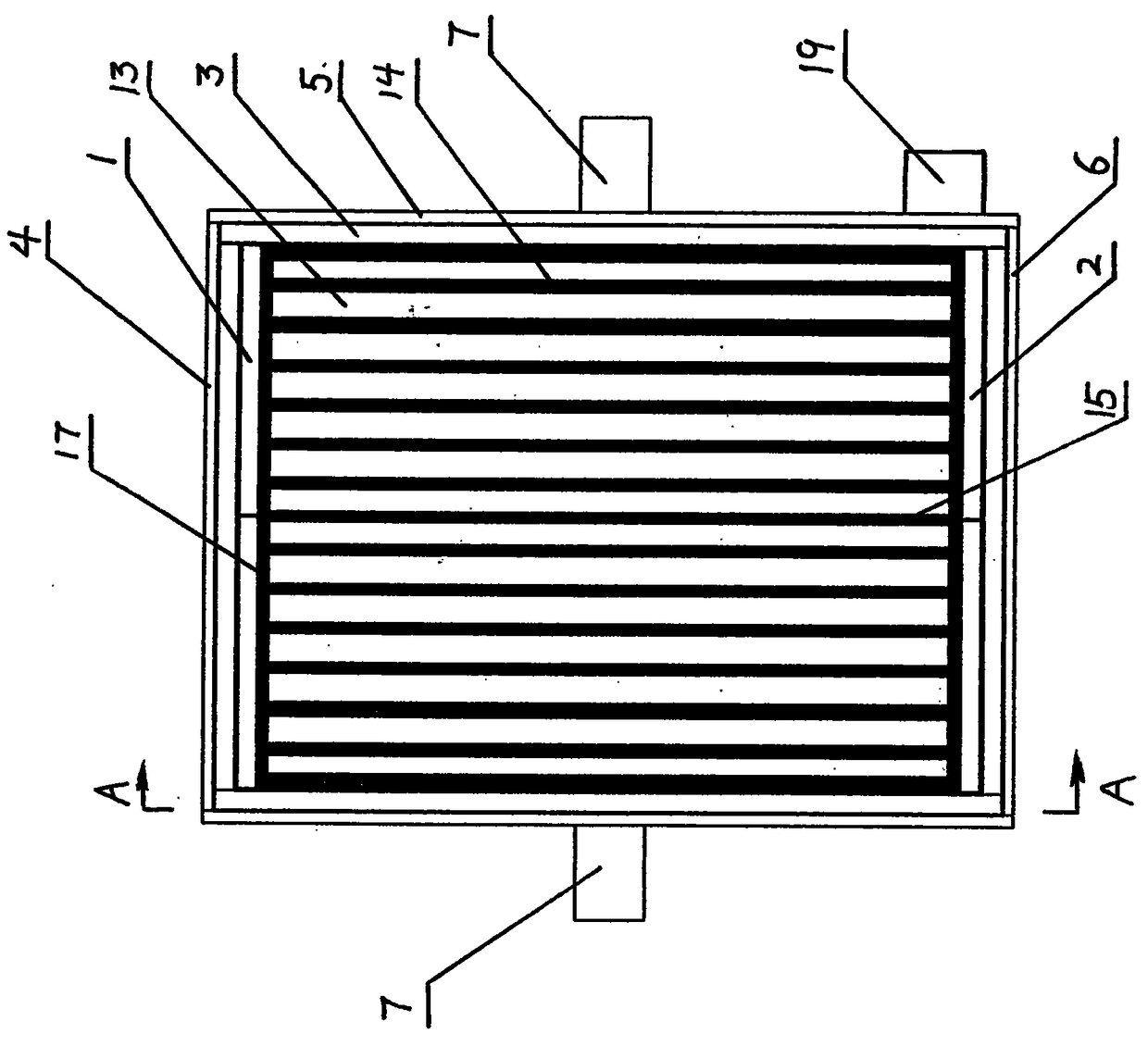
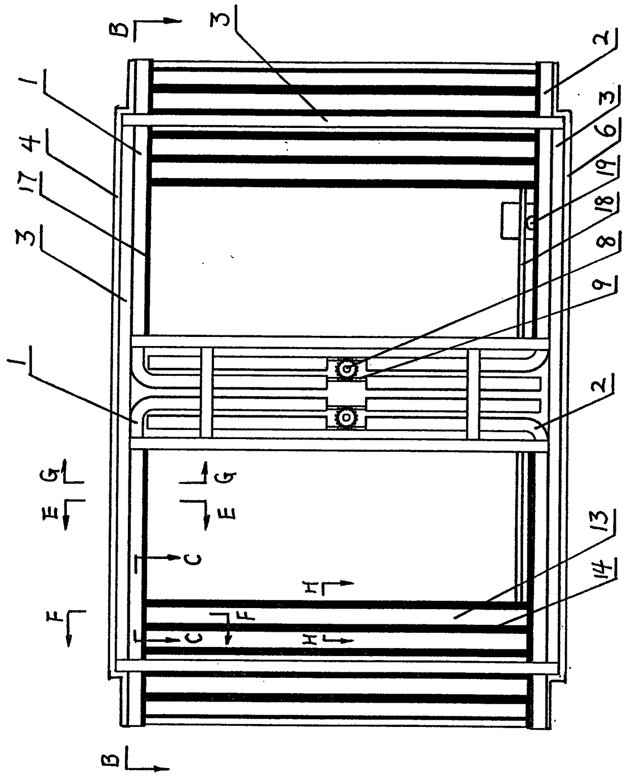
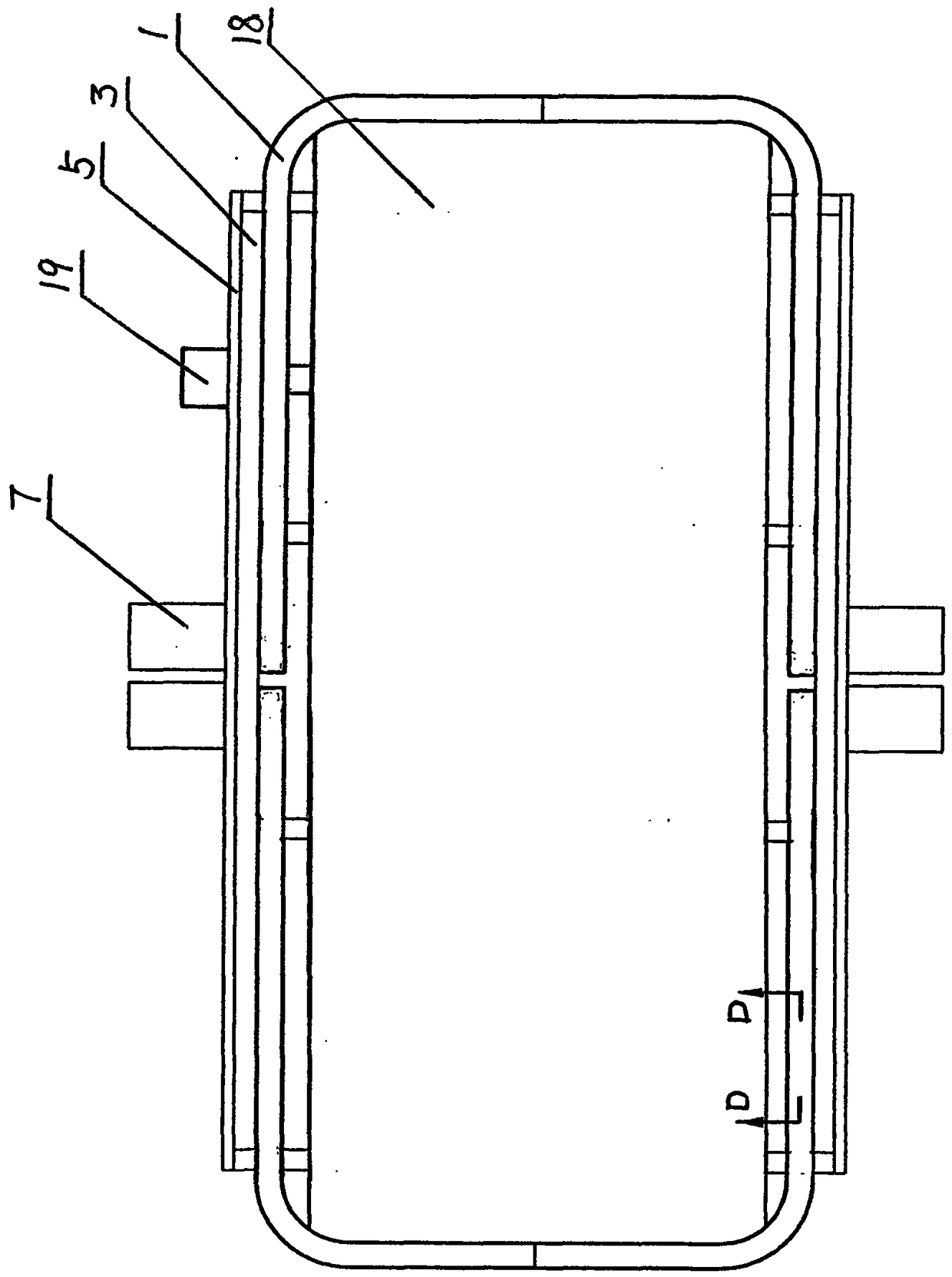
[0026] Such as Figure 1 to Figure 9 Shown, this cold storage delivery door structure of the present invention consists of upper chain guide rail 1, lower chain guide rail 2, main body frame 3, top plate 4, side plate 5, bottom plate 6, sprocket motor 7, sprocket wheel 8, transmission chain 9, Drive chain 10, chain connecting block 11, connecting pin shaft 12, door panel 13, telescopic connector 14, extrude sealing strip 15, anti-cold bridge connector 16, insulation strip 17, conveyor belt 18, transmission motor 19 to form, will The upper chain guide rail 1 is installed on the upper part of the main frame 3, the lower chain guide rail 2 is installed on the lower part of the main frame 3; the top plate 4 is installed on the upper part of the main frame 3, and the side plate 5 is installed on the upper part of the main frame On both sides of the main body frame 3, the bottom plate 6 is installed on the bottom of the main frame 3; the sprocket motor 7 is installed on the side pla...
PUM
Abstract
The invention relates to a conveying door structure of a cold storage. The conveying door structure is composed of an upper chain guide rail, a lower chain guide rail, a main frame, a top plate, lateral plates, a bottom plate, a chain wheel motor, a chain wheel, a conveying chain, a driving chain, a connection block, a connection pin shaft, a door panel, a telescopic connector, an extrusion sealing strip, an anti-cold-bridge connector, an insulation strip, a conveying belt and a conveying motor. The upper chain guide rail is arranged at the upper portion of the main frame, the lower chain guide rail is arranged at the lower portion of the main frame, the top plate is arranged at the upper portion of the main frame, the lateral plates are arranged on the two sides of the main frame, and the bottom plate is arranged at the lower portion of the main frame. The chain motor is arranged on the lateral plates, the conveying belt is arranged on the bottom plate, and the conveying motor is arranged on the side plates and connected with the conveying belt. An ordinary cold storage door structure is improved, opening and closing of a cold storage door and entrance and exit of cargos can be automatically controlled in the whole process, and the energy-saving and efficient conveying door structure of the cold storage is reliable and stable in operation and short in consumed time in the opening and closing process.
Description
Technical field: [0001] The invention relates to a conveying door structure, in particular to a cold storage conveying door structure. Background technique: [0002] Ordinary cold storage doors generally use sliding doors or rolling doors. The use of ordinary sliding doors is easy to cause heat exchange with the outside world when opening and closing, resulting in leakage of cooling capacity in the cold storage; and there is no automatic function. The use of ordinary automatic shutter doors is not only costly, but also takes a long time to go up and down the shutter, causing the goods to wait outside the door easily, resulting in accumulation, resulting in low work efficiency, and because the process of rolling up and down the shutter takes a long time, it will also cause cold storage. A large amount of cold energy leaks out. [0003] Purpose of the invention: [0004] The object of the present invention is to provide a cold storage delivery door structure, which improves...
Claims
Application Information
Patent Timeline
Application Date:The date an application was filed.
Publication Date:The date a patent or application was officially published.
First Publication Date:The earliest publication date of a patent with the same application number.
Issue Date:Publication date of the patent grant document.
PCT Entry Date:The Entry date of PCT National Phase.
Estimated Expiry Date:The statutory expiry date of a patent right according to the Patent Law, and it is the longest term of protection that the patent right can achieve without the termination of the patent right due to other reasons(Term extension factor has been taken into account ).
Invalid Date:Actual expiry date is based on effective date or publication date of legal transaction data of invalid patent.