
Heat source machine formed by connecting gas water heaters in parallel and control method

A gas water heater and water heater technology, applied in water heaters, fluid heaters, lighting and heating equipment, etc., can solve the problems of large boiler system, unstable water temperature, and high investment cost, and achieve simple system structure and constant water temperature. Effect

Inactive Publication Date: 2014-12-10
成都前锋电子有限责任公司
View PDF6 Cites 26 Cited by
  • Summary
  • Abstract
  • Description
  • Claims
  • Application Information

AI Technical Summary

Problems solved by technology

[0002] At present, there are many places that need to supply large flow of hot water, such as constant temperature swimming pools, hotels, hotels, etc., which may require a large flow of constant temperature hot water in a short period of time, and the existing single gas water heater is limited by the heating load. It cannot meet the demand for large-flow constant-temperature hot water; although large-scale boilers can provide large-flow hot water, the water temperature is not constant, and a water storage tank is required, and heat loss will occur during the heat preservation process. The boiler system is bulky and takes up space, requiring special care. Frequent maintenance, high operating noise, high cost of use, regular inspection is required
The existing parallel water heater units in the prior art all need to be equipped with a constant temperature water tank, and the constant water temperature is controlled by corresponding supporting circulating water pumps, temperature probes, stop valves, water replenishment solenoid valves, etc. The booster pump and circulation pipeline have complex structures and high investment costs, and the maintenance costs for the constant temperature water tank and corresponding instruments are not small

Method used


Image

  • Heat source machine formed by connecting gas water heaters in parallel and control method
  • Heat source machine formed by connecting gas water heaters in parallel and control method

Examples


Embodiment 1

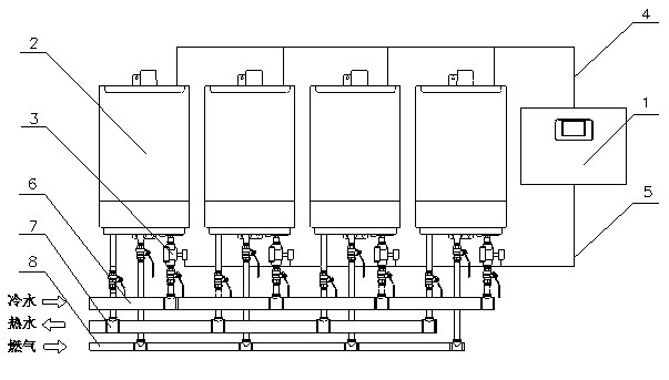
[0020] Such as figure 1 As shown, a heat source machine in which gas water heaters are connected in parallel includes a main water inlet pipe 6, a hot water converging pipe 7, a main gas inlet pipe 8, a plurality of gas water heaters 2 and a system controller 1, and the plurality of gas water heaters 2 pass through The total water inlet pipe 6, the hot water converging pipe 7, and the total gas inlet pipe 8 are connected in parallel; each water heater is equipped with a collection water flow sensor, an inlet water temperature detector and an outlet water temperature detector, and the communication bus 4 and the setting The signal converter on the communication bus 4 is connected to the system controller 1, and the cold water pipe of the gas water heater 2 is provided with a water inlet solenoid valve 3, and the water inlet solenoid valve 3 is connected to the system control through the water inlet switch control line 5. Connector 1.

[0021] Such as figure 1 As shown, the ...

Embodiment 2

[0036] In this example, four Qianfeng brand JSQ36-F7 intelligent constant-temperature forced-vent gas rapid water heaters are used to form a heat source machine. The maximum hot water production capacity of a single water heater is 18kg / min (at a temperature rise of The hot water production capacity is 2kg / min (at a temperature rise of 25°C). Therefore, the maximum hot water production capacity of this heat source unit is 4x18=72kg / min (at a temperature rise of 25°C).

[0037] The control process of the heat source machines formed by gas water heaters connected in parallel in this embodiment is:

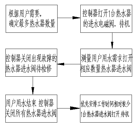
[0038] First, according to the user's needs, set the required hot water temperature to 45°C through the system controller. The tap water temperature of the user is 20°C, therefore, the water inflow of each gas water heater is just numerically the same as the hot water production capacity of the water heater. According to the situation of the user's system, the system controller fir...

Embodiment 3

[0048] In this example, four Qianfeng brand JSQ36-F7 intelligent constant-temperature forced-vent gas rapid water heaters are used to form a heat source machine. The maximum hot water production capacity of a single water heater is 18kg / min (at a temperature rise of The hot water production capacity is 2kg / min (at a temperature rise of 25°C). Therefore, the maximum hot water production capacity of this heat source unit is 4x18=72kg / min (at a temperature rise of 25°C).

[0049] The control process of the heat source machines formed by gas water heaters connected in parallel in this embodiment is:

[0050] First, according to the user's needs, set the required hot water temperature to 45°C through the system controller. The tap water temperature of the user is 20°C, therefore, the water inlet flow of each water heater is just numerically the same as the hot water production capacity of the water heater. According to the situation of the user's system, the system controller fir...


PUM


Abstract

The invention discloses a heat source machine formed by connecting gas water heaters in parallel and a control method. The heat source machine comprises a main water inlet pipe, a hot water convergence pipe, a main gas inlet pipe, gas water heaters and a system controller. The gas water heaters are connected in parallel through the main water inlet pipe, the hot water convergence pipe and the main gas inlet pipe. Each gas water heater is internally provided with a water flow collecting sensor, a water inlet temperature detector and a water outlet temperature detector and is connected with the system controller through a communication bus and a signal converter arranged on the communication bus. A water inlet electromagnetic valve is arranged on a cold water pipe of each gas water heater and connected with the system controller through a water inlet switch control line. During working, data of each gas water heater are transmitted to the system controller, the number of the gas water heaters needing to work is worked out, the system structure is simple, installation is convenient, the water temperature is constant, no constant temperature water tank is needed, and safety is high.

Description

technical field [0001] The invention relates to a heat source machine, in particular to a heat source machine formed by parallel connection of gas water heaters and a control method. Background technique [0002] At present, there are many places that need to supply large flow of hot water, such as constant temperature swimming pools, hotels, hotels, etc., which may require a large flow of constant temperature hot water in a short period of time, and the existing single gas water heater is limited by the heating load. It cannot meet the demand for large-flow constant-temperature hot water; although large-scale boilers can provide large-flow hot water, the water temperature is not constant, and a water storage tank is required, and heat loss will occur during the heat preservation process. The boiler system is bulky and takes up space, requiring special care. Frequent maintenance, high operating noise, high cost of use, and regular inspections are required. The existing para...

Claims


Application Information

Patent Timeline
Patent Type & Authority Applications(China)
IPC IPC(8): F24H1/00F24H9/20
Inventor 孙俊良岳志毅朱宁东卢捍红陈敦勇
Owner 成都前锋电子有限责任公司
Learn More