Strengthened heat transfer gravity assisted heat pipe

A gravitational heat pipe and heat transfer enhancement technology, applied in the field of heat pipes, can solve the problems of affecting condensation efficiency and difficulty in obtaining dropwise condensation, and achieve the effects of improving heat transfer efficiency, increasing condensation efficiency and reducing heat transfer thermal resistance.

Active Publication Date: 2014-12-10
SOUTHEAST UNIV
View PDF5 Cites 6 Cited by
  • Summary
  • Abstract
  • Description
  • Claims
  • Application Information

AI Technical Summary

Problems solved by technology

Another way to enhance condensation heat transfer is to maintain dropwise condensation. For this purpose, a hydrophobic coating can be coated on the wall, or a small amount of oily additives can be sprayed into the steam, but it is difficult to obtain durable droplet condensation. The thickness of the liquid film directly affects the entire condensation efficiency, how to reduce the thickness of the liquid film in the condensation section of the heat pipe is a problem to be further studied

Method used


Image

  • Strengthened heat transfer gravity assisted heat pipe
  • Strengthened heat transfer gravity assisted heat pipe
  • Strengthened heat transfer gravity assisted heat pipe

Examples


Embodiment Construction

[0019] The technical solution of the present invention will be described in detail below in conjunction with the accompanying drawings.

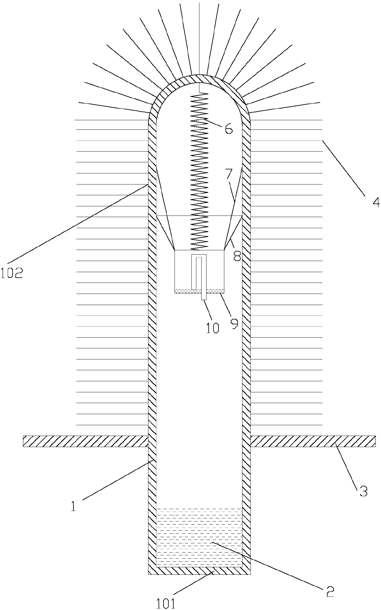
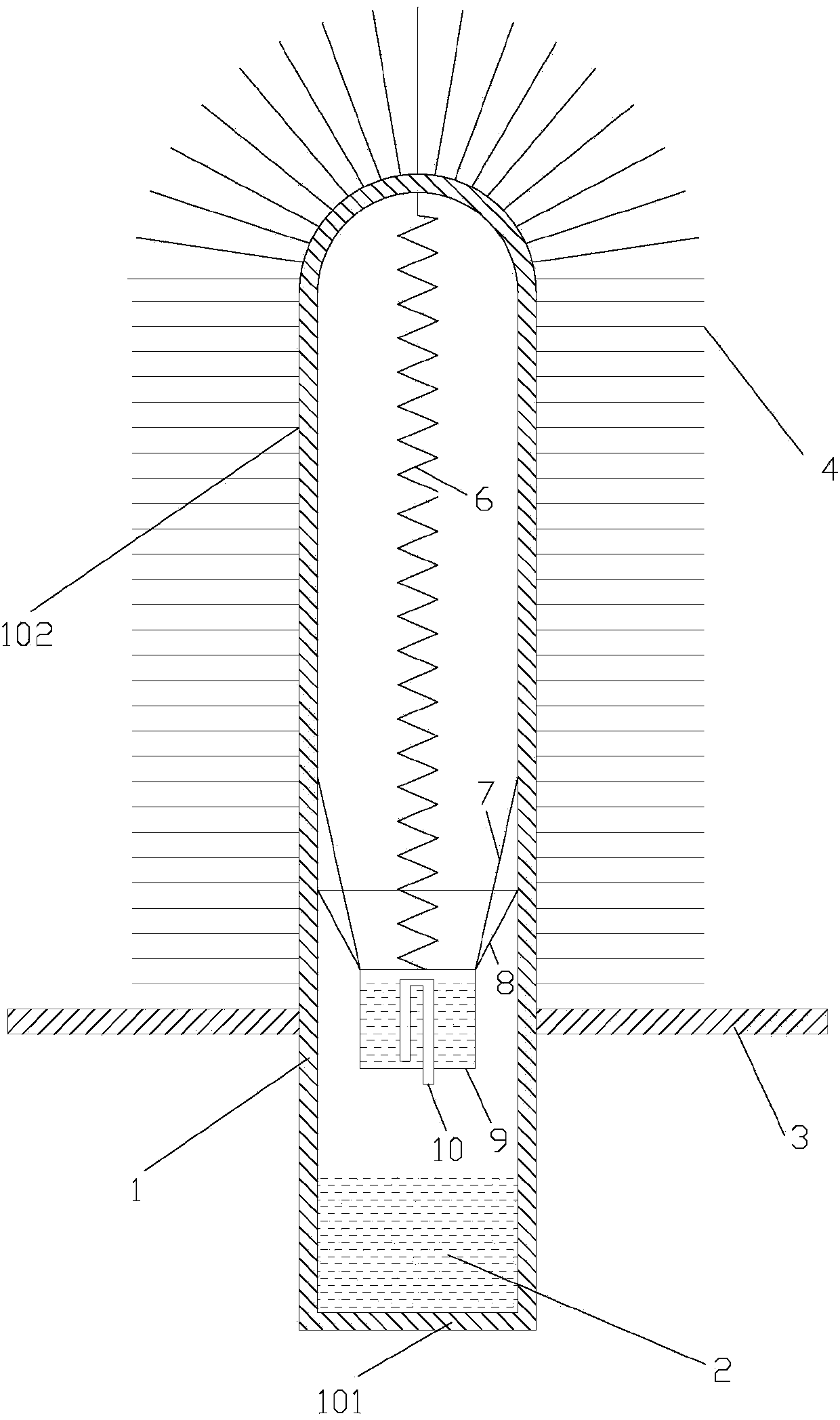
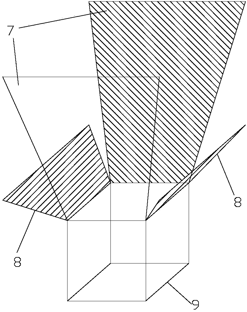
[0020] Such as Figure 1 to Figure 6 As shown, a heat transfer enhanced gravity heat pipe of the present invention includes a pipe body 1, a liquid working medium 2, a separator 3, cooling fins 4 and a liquid scraping device. The partition 3 is fixedly connected to the outer wall of the pipe body 1 , and the partition 3 is located below the middle of the pipe body 1 . The part of the pipe body below the partition 3 is the evaporation section 101 , and the part of the pipe body above the partition 3 is the condensation section 102 . The cooling fins 4 are fixedly connected to the outer wall of the condensation section 102 , and the liquid working medium 2 is located inside the evaporation section 101 . The liquid scraping device is located inside the pipe body 1 . The liquid scraping device includes a spring 6, two first return plates 7, t...


PUM


Abstract

The invention discloses a strengthened heat transfer gravity assisted heat pipe comprising a pipe body, a working fluid, partitions, radiating fins and a fluid scraping device. The partitions are fixedly connected on the outer wall surface of the pipe body; the radiating fins are fixedly connected on the outer wall of a condensation section, and the working fluid is located inside an evaporation section; the fluid scraping device comprises a spring, two first backflow plates, two second backflow plates, a lifting tank and a siphon pipe, one end of the spring is fixedly connected on the inner wall surface of the top of the pipe body while the other end is fixed to the bottom of the lifting tank, the siphon pipe is fixedly connected on the bottom surface of the lifting tank, and the bottom ends of the first backflow plates and the second backflow plates are fixedly connected on the periphery of the top end of the lifting tank; flow guide bosses are arranged at two side edges of each of the first backflow plates and the second backflow plates, and a rubber scraping strip is mounted at the top end of each of the first and second backflow plates. Gas and fluid in the heat pipe can circulate effectively, heat transfer efficiency can be improved effectively, and the strengthened heat transfer gravity assisted heat pipe can be well applied to occasions of cooling of computer chips, instrument and equipment.

Description

technical field [0001] The invention belongs to the technical field of heat pipes, in particular, it relates to a heat transfer-enhanced gravity heat pipe, Background technique [0002] Heat pipe technology is widely used in aerospace, military and other industries. Since it was introduced into the radiator manufacturing industry, people have changed the design ideas of traditional radiators. Gravity heat pipe is the most commonly used form of heat pipe. Its working principle is that when the evaporation section of the heat pipe is heated, the working medium in the heat pipe evaporates and vaporizes. Return to the evaporation section. In this endless cycle, heat is transferred from one end to the other. The heat pipe has a large heat transfer capacity. The heat pipe cleverly organizes the two phase transition processes of boiling and condensation with small thermal resistance, so that its equivalent thermal conductivity is several times or even thousands of times that of c...

Claims


Application Information

Patent Timeline
Patent Type & Authority Applications(China)
IPC IPC(8): F28D15/02
Inventor 杨柳杜垲鲁洁明刘腾陈谢磊张小松
Owner SOUTHEAST UNIV
Why Eureka
Try Eureka