
Specific stationary fixture for detecting wave buoy

A technology of wave buoys and fixed fixtures, which can be used in measuring devices, surveying and navigation, open-air water source surveys, etc., can solve the problems of enlarged safety hazards, different lengths, lack of equipment, etc., and achieve the effect of improving safety performance and accuracy

Active Publication Date: 2014-12-10
中船鹏力(南京)大气海洋信息系统有限公司
View PDF5 Cites 2 Cited by
  • Summary
  • Abstract
  • Description
  • Claims
  • Application Information

AI Technical Summary

Problems solved by technology

However, the deformation still exists. When this structure rotates at a high speed, the potential safety hazard caused by the deformation will be magnified, and there are still safety problems for people, instruments or equipment; the clamping of the buoy and the clamping of the radial adjustment screw are uniform. It is operated manually, and the length of the tightening adjustment screw is different, so that the center of the buoy after clamping is not on the fixed axis surface of the ring clamp, and the relative position is randomly distributed.
This directly affects the accuracy and uniformity of the wave height of the main verification data of the wave buoy; at the same time, this type of fixture does not have the 16 circumferential angle detection points required by the verification standard without taking off the clamp when doing the wave direction verification test The positioning function of

Method used


Image

  • Specific stationary fixture for detecting wave buoy
  • Specific stationary fixture for detecting wave buoy
  • Specific stationary fixture for detecting wave buoy

Examples


Embodiment Construction

[0019] Below in conjunction with accompanying drawing, the technical scheme of the present application is described in detail:

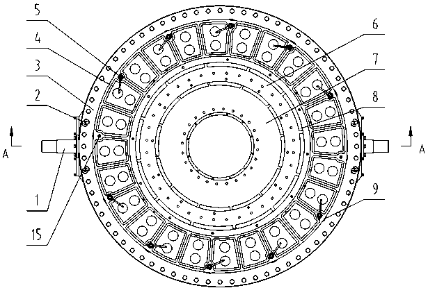
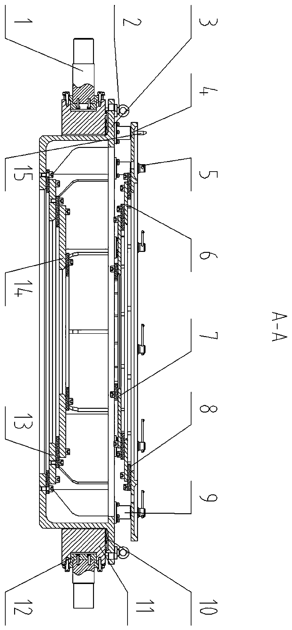
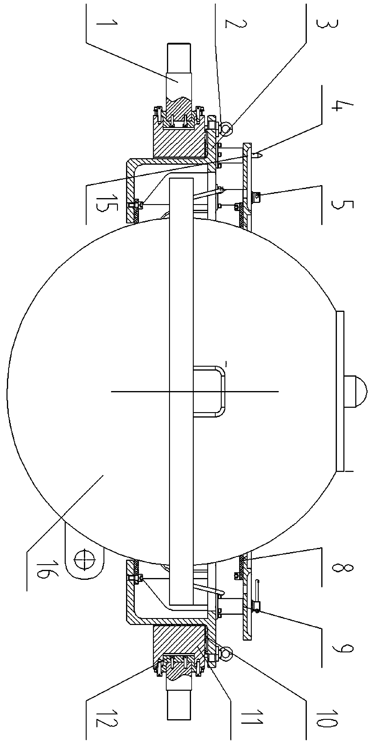
[0020] like figure 1 As shown, the special fixing fixture for wave buoy detection includes rotating shaft 1, azimuth positioning pin 2, rotating body seat 3, buoy upper pressure plate, fixing bolt 5, rubber gasket 8, screw sleeve 9, azimuth turntable 11, and rotating shaft flange 12. The lower pressure plate of the buoy and the positioning pin 15, wherein the rotating shaft 1 and the rotating shaft flange 12 are coaxially installed on both sides of the azimuth turntable 11 after assembly; 2 Lock the position of the rotating body seat 3; after the upper pressure plate of the buoy is assembled with the rubber gasket 8, it is fixed on the upper part of the rotating body seat 3 through the fixing bolt 5 and the screw sleeve 9, and the rotating body is locked by the positioning pin 15 The position on the seat 3; the lower pressure plate of the buoy is as...


PUM


Abstract

The application discloses a specific stationary fixture for detecting a wave buoy. The specific stationary fixture comprises a fixed rotating shaft, positioning pins, a rotating body seat, upper buoy pressing discs, fixed bolts, rubber gaskets, thread sleeves, steel ball rolling wheels, a positioning rotating table, a rotating shaft flange disc, lower buoy pressing discs and positioning pins, wherein the fixed rotating shaft and the rotating shaft flange disc are fixedly mounted on two sides of the positioning rotating table after being assembled; the steel ball rolling wheels are uniformly mounted on an upper machining mounting surface of the positioning rotating table and are required to be located in one plane; the rotating body seat is fixedly arranged on the positioning rotating table by virtue of cooperation of the fixed bolts and the thread sleeves, and is locked by the positioning pins. The specific stationary fixture for detecting the wave buoy has the beneficial effects that the principle is advanced, the design is skillful, and the operation is safe and rapid; the center of the fixed wave buoy is in high superposition with a fixed axial surface of the combined fixture, so that the detection accuracy is guaranteed; meanwhile, the circumferential rotation and positioning can be easily carried out during a wave direction detection test.

Description

technical field [0001] This application relates to the technical field of marine wave buoy measurement and verification, specifically a special fixing fixture for wave buoy detection. Background technique [0002] Wave is one of the six elements of ocean hydrology. The accuracy of ocean wave data and data has a major impact on ocean engineering, marine traffic, marine military activities, mariculture and fishing, marine environmental protection, and marine research. In order to strengthen the measurement of ocean waves, relevant departments and units have successively introduced various wave buoys from abroad; at the same time, our country is also actively accelerating the practical application of self-developed wave buoys. In order to ensure the accuracy, reliability and unity of the wave buoy measurement data, my country has also completed the establishment of the ocean wave buoy verification device. The buoy fixture structure used in the device is: a ring frame composed ...

Claims


Application Information

Patent Timeline
Patent Type & Authority Applications(China)
IPC IPC(8): G01C25/00G01C13/00
CPCG01C13/002G01C25/00
Inventor 朱飞徐喜东谢向前施春荣薛宜童
Owner 中船鹏力(南京)大气海洋信息系统有限公司
Learn More