
Power measuring circuit

A power measurement and circuit technology, applied in the field of electrical calibration pyroelectric radiometers, can solve the problems of measurement error, being susceptible to noise interference, and reducing measurement accuracy, so as to improve the signal-to-noise ratio, ensure accuracy, and suppress noise. Effect

Inactive Publication Date: 2014-12-10
UNIV OF SHANGHAI FOR SCI & TECH
View PDF5 Cites 3 Cited by
  • Summary
  • Abstract
  • Description
  • Claims
  • Application Information

AI Technical Summary

Problems solved by technology

When the signal to be measured is strong, the electric heating signal automatically generated inside the electric calibration radiometer is also relatively strong, and the measurement accuracy is relatively high at this time; The electric heating signal is also relatively weak, and it is easily disturbed by noise, which will cause measurement errors and reduce the accuracy of measurement

Method used


Image

  • Power measuring circuit
  • Power measuring circuit
  • Power measuring circuit

Examples


Embodiment Construction

[0023] The specific implementation manners of the present invention will be described below in conjunction with the accompanying drawings.

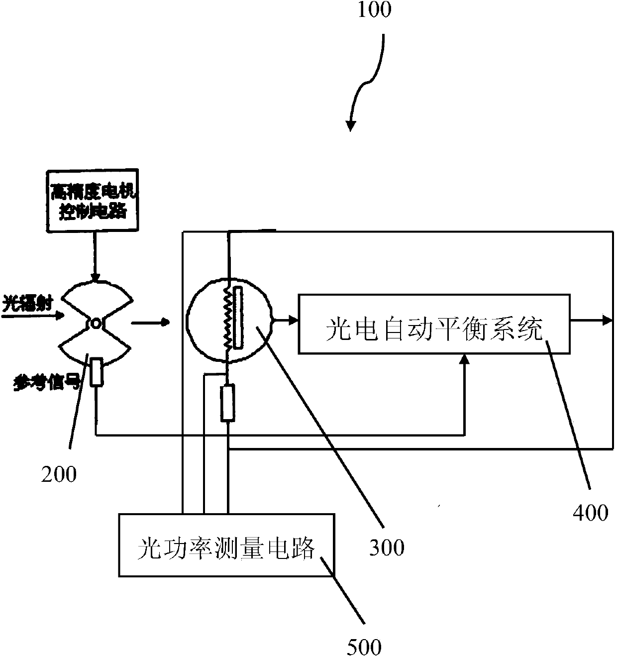
[0024] figure 1 It is a structural schematic diagram of the electrical calibration pyroelectric radiometer of this embodiment.

[0025] Such as figure 1 As shown, the electrical calibration pyroelectric radiometer 100 includes a high stability optical chopper 200, a pyroelectric detector 300, a photoelectric automatic balancing system 400 and an optical power measurement circuit 500, and the high stability optical chopper 200 is used for After the optical signal is modulated, it is irradiated to the pyroelectric detector 300 and provides a reference signal for the phase-locked circuit in the photoelectric automatic balancing system 400. The input end of the photoelectric automatic balancing system 500 is connected to the pyroelectric detector 300 for The input optical signal of the electric detector 300 is converted into an electric hea...


PUM


Abstract

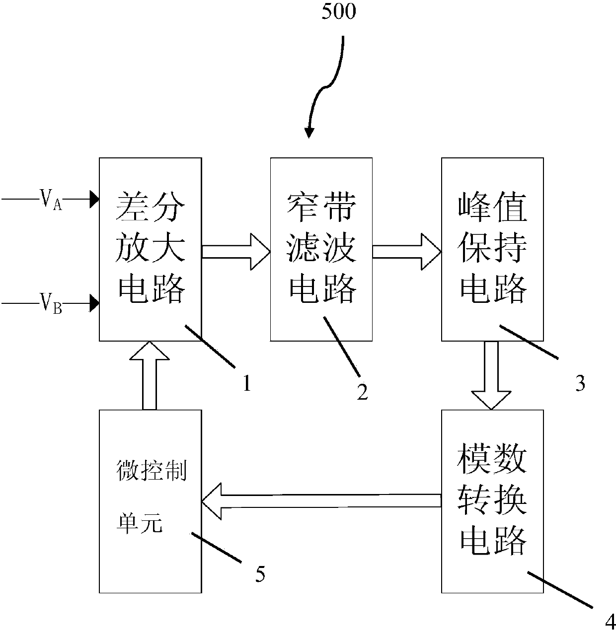
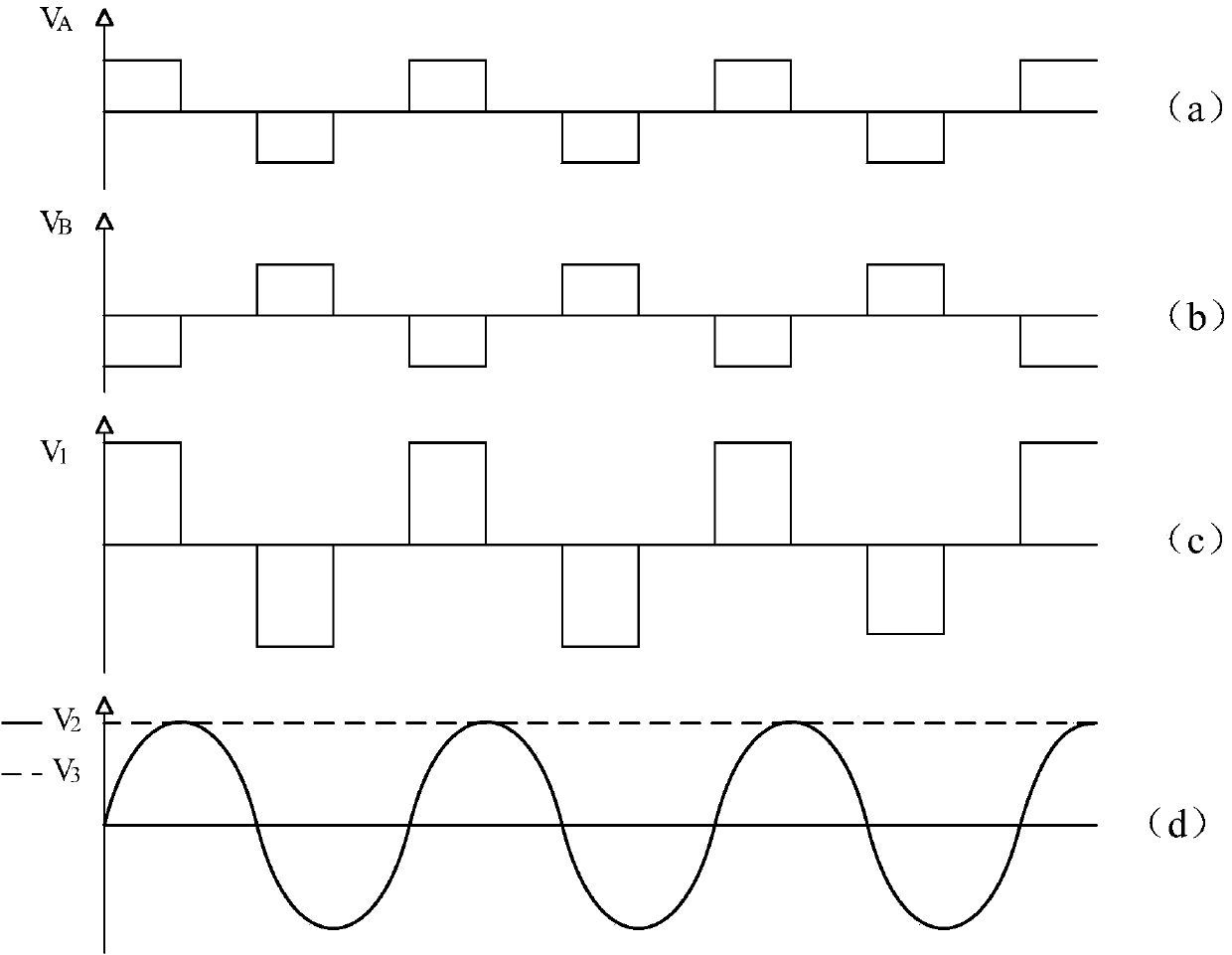
The invention provides a power measuring circuit which comprises a differential amplification circuit, a filter circuit, a peak value retaining circuit, an analog-digital conversion circuit and a micro-control component. The differential amplification circuit differentially outputs electric heating signals at two ends of a pyroelectric detector, the filter circuit extracts effective signals from the signals output by the differential amplification circuit and restrains the noise overlaid on the signals of the differential amplification circuit to increase signal to noise ratio, the peak value retaining circuit extracts the amplitude information of the effective signals, the analog-digital conversion circuit converts the amplitude information of the effective signals into digital signals and transmits the digital singles to the micro-control component, and the micro-control component controls the analog-digital conversion circuit and adjusts the amplification times of the differential amplification circuit. The power measuring circuit has the advantages that strong signals can be detected while measuring accuracy of weak signals is guaranteed, and the dynamic measuring range of the system is increased.

Description

technical field [0001] The invention belongs to the field of electric calibration pyroelectric radiometers, in particular to a power measurement circuit of electric calibration pyroelectric radiometers. Background technique [0002] The electrical calibration pyroelectric radiometer is a high-precision absolute radiometer for measuring optical radiation power. The power measurement circuit is an important part of the radiometer, which is used to measure the electric heating power equivalent to the optical power. The electric heating signal applied to both ends of the pyroelectric detector is a set of alternating polarity voltage signals with equal amplitude and opposite phase. By measuring the voltage amplitude U at both ends of the pyroelectric detector, it can be obtained by Calculate the electric heating power value. [0003] Under normal circumstances, U first obtains the voltage difference between the two ends of the pyroelectric detector through a differential circui...

Claims


Application Information

Patent Timeline
Patent Type & Authority Applications(China)
IPC IPC(8): G01J1/42
Inventor 高鹏飞瑚琦郭汉明王琦
Owner UNIV OF SHANGHAI FOR SCI & TECH
Learn More