
A Bidirectional Pull Fiber Bragg Grating Humidity Sensor

A technology of humidity sensor and optical fiber grating, which is applied in the field of sensors, can solve the problem of point-by-point detection of the lack of optical fiber grating humidity sensor, and can not solve the problem of prestressed loading of optical fiber grating well, so as to solve the problem of prestressed loading and environmental humidity Point-by-point detection of problems, improvement of internal stress variation and humidity detection accuracy, and improvement of moisture absorption efficiency

Inactive Publication Date: 2016-08-17
XIAN UNIV OF SCI & TECH
View PDF7 Cites 0 Cited by
  • Summary
  • Abstract
  • Description
  • Claims
  • Application Information

AI Technical Summary

Problems solved by technology

The disadvantage of this method is that, in order to ensure the coating amount of the hygroscopic material, the polyimide on the surface of the fiber grating can only be about tens of microns in thickness after repeated coating. , the wavelength shift is less than 0.1 nm
At the same time, due to the increase in the length of the fiber grating, the fiber grating humidity sensor made by this method lacks the ability of point-by-point detection
On the other hand, the disadvantage of this humidity sensor is that it cannot solve the prestressed loading problem of the fiber grating well.

Method used


Image

  • A Bidirectional Pull Fiber Bragg Grating Humidity Sensor
  • A Bidirectional Pull Fiber Bragg Grating Humidity Sensor
  • A Bidirectional Pull Fiber Bragg Grating Humidity Sensor

Examples


Embodiment Construction

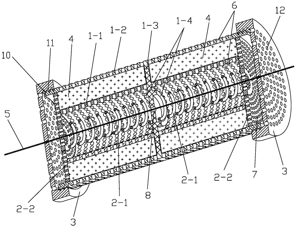
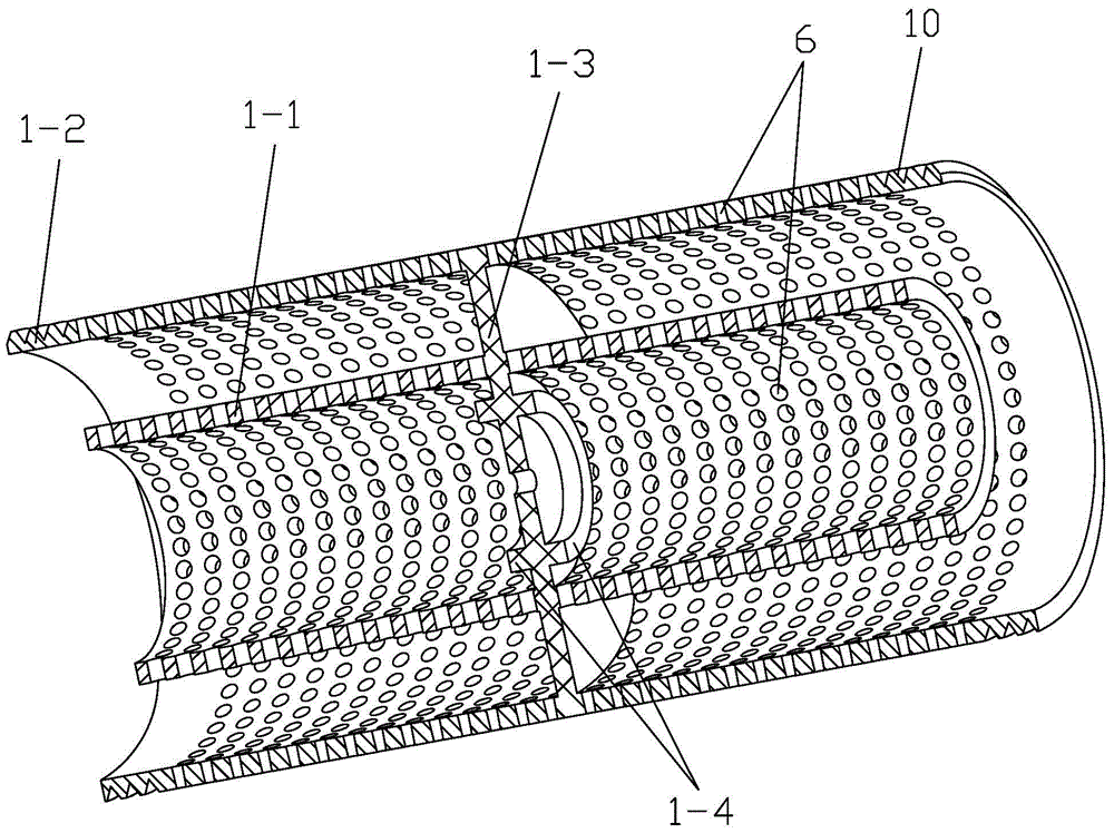
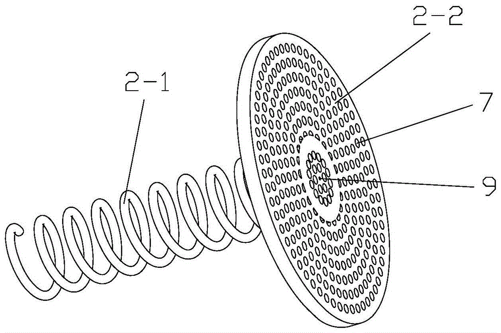
[0033] like Figure 1 to Figure 5 As shown, the present invention includes a double-layer cylindrical shell and a fiber grating 5. The double-layer cylindrical shell includes an outer shell 1-2, an inner shell 1-1 and a partition 1-3, and the outer shell 1-2 and the inner shell 1- 1 are open at both ends, the partition 1-3 is fixed in the middle of the outer casing 1-2, the partition 1-3 passes through the middle of the inner casing 1-1 and divides the double-layer cylindrical shell into equal first The cavity and the second cavity, the partition 1-3 is fixedly connected with the inner shell 1-1, both ends of the outer shell 1-2 protrude from both ends of the inner shell 1-1, and the outer shell 1-2 2 and the inner shell 1-1 are provided with a plurality of first through holes 6, and the middle parts of both sides of the partition 1-3 are fixed with a spring fixing table 1-4, and the first cavity and the second cavity A spring top plate is arranged symmetrically in the body, ...


PUM


Abstract

The invention discloses a two-way traction fiber bragg grating humidity sensor which comprises a double-layer cylindrical shell and a fiber bragg grating, the double-layer cylindrical shell comprises an outer shell, an inner shell and a clapboard, the clapboard is fixed in the middle of the outer shell, penetrates through the middle of the inner shell, and divides the double-layer cylindrical shell into a first cavity and a second cavity which are the same, a first through hole is formed in the outer shell and the inner shell, a spring fixing station is fixed in the middle of each of the two sides of the clapboard, the first cavity and the second cavity are internally and symmetrically provided with spring top plates, the spring top plate comprises a spring and a top plate, the spring is arranged in the inner shell, the top plate is arranged at the end part of the inner shell, the two ends of the spring are respectively connected with the spring fixing station and the top plate, a second through hole is formed in the top plate, a moisture absorption expansion block is tightly filled in a space formed by the outer shell, the inner shell and the top plate, a first via hole is formed in the center of the top plate, a second via hole is formed in the center of the clapboard, and the fiber bragg grating penetrates through the first via hole and the second via hole and is connected fixedly with the top plate. The two-way traction fiber bragg grating humidity sensor is high in detection precision, the prestress is convenient to load, and the ambient humidity can be detected point by point.

Description

technical field [0001] The invention relates to a sensor, in particular to a bidirectional pulling optical fiber grating humidity sensor. Background technique [0002] With the rapid development of science and technology, people's demand for accurate measurement of physical parameters in nature is becoming more and more urgent. During this process, fiber optic sensing technology has also been fully developed and widely used, including the technology of fiber gratings for sensing and measurement. As we all know, fiber gratings can accurately measure temperature, stress, strain, displacement, acceleration, etc., and the measurement of environmental humidity is a newly developed field, and it faces many scientific and engineering problems that need to be solved urgently. Traditional humidity sensors use functional materials to absorb environmental moisture and change their electrical parameters such as resistance and capacitance to detect humidity, while fiber Bragg gratings m...

Claims


Application Information

Patent Timeline
Patent Type & Authority Patents(China)
IPC IPC(8): G01N21/17
Inventor 刘海强
Owner XIAN UNIV OF SCI & TECH
Learn More