
Antenna device and method applied under shielding condition of tunnel inspection well interior cover

An antenna device and inspection well technology, which is applied in the field of antenna devices, can solve problems such as communication interruption, failure to obtain early warning information, high-gain antennas that cannot achieve shielding, etc., and achieve reliable and stable transmission effects

Active Publication Date: 2014-12-10
康威通信技术股份有限公司
View PDF3 Cites 5 Cited by
  • Summary
  • Abstract
  • Description
  • Claims
  • Application Information

AI Technical Summary

Problems solved by technology

The shielding effect of the outer cast iron cover on the antenna signal is obvious, and the simple use of high-gain antennas cannot achieve the purpose of penetrating the shielding of the cast iron outer cover
[0003] Due to the shielding effect of the outer cast iron manhole cover, the received signal of the wireless signal in the tunnel environment is very weak, which often leads to the interruption of the communication between the inner sub-cover in the tunnel and the outside world, and the outside staff cannot automatically obtain the status of the monitoring inner sub-cover. When the manhole cover is lost or damaged, outsiders cannot obtain early warning information through the inner cover, thus losing the monitoring function of the inner cover and the outer manhole cover

Method used


Image

  • Antenna device and method applied under shielding condition of tunnel inspection well interior cover
  • Antenna device and method applied under shielding condition of tunnel inspection well interior cover
  • Antenna device and method applied under shielding condition of tunnel inspection well interior cover

Examples


Embodiment Construction

[0026] Below in conjunction with accompanying drawing and embodiment the present invention will be further described:

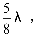
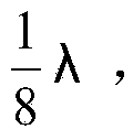
[0027] Figure 1-3 shown as Schematic diagram of the assembly of the antenna 5 and the inner sub-cover 1, the antenna and the inner sub-cover are fixed together in parallel, and the combined parts include two Antenna 5 (λ is the wavelength of GSM antenna frequency band 900Mhz), antenna tee 2, antenna casing 3, pipe card 4, inner sub-cover 1, tee shell 6, junction plate 7, antenna feeder 8.

[0028] When assembling, place the two The antenna 5 and the antenna feeder 8 are respectively welded on a connecting plate, and then the assembly of these parts is put into the tee shell 6 . After being fixed, the antenna sleeve 3 should be inserted to put the antenna tee shell 6 around the groove in the inner sub-cover 1, and be fixed with the pipe clamp 4. The two antennas are collinearly arranged, and the antennas are arranged parallel to the inner manhole cover...


PUM


Abstract

The invention discloses an antenna device and a method applied under a shielding condition of a tunnel inspection well interior cover. The antenna device applied under the shielding condition of the tunnel inspection well interior cover comprises antennae, an antenna feeder line and a junction plate, wherein the antennae are respectively arranged at two ends of the junction plate, the antennae at the two ends of the junction plate are collinearly arranged, the antenna feeder line is arranged on the junction plate and along the direction vertical to the antennae, and an assembly unit of the antennae, the antenna feeder line and the junction plate is placed in a three way housing. The antenna device and the method applied under the shielding condition of the tunnel inspection well interior cover have the advantages of achieving the purpose of breaking shielding of a cast iron outer cover by scattering and reflecting signals under a tunnel environment through design of the antennae and integral installation of the antennae and the interior cover, achieving wireless communications between the interior and the exterior of a tunnel, and achieving reliable and stable information transmission.

Description

technical field [0001] The invention relates to an antenna device, in particular to an antenna device and a method applied to the shielding condition of a sub-cover in a tunnel inspection shaft. Background technique [0002] Power tunnels are generally located in an environment with a depth of 2 or 3 meters underground. At present, antennas in the GSM900MHz frequency band used in tunnel environments mostly use vertical polarization with narrow lobe pointing width and concentrated energy. communication. For tunnel inspection wells, the wellhead is equipped with an outer cast iron manhole cover and an inner sub-cover. The shielding effect of the outer cast iron cover on the antenna signal is obvious, and the simple use of high-gain antennas cannot achieve the shielding purpose of penetrating the cast iron outer cover. [0003] Due to the shielding effect of the outer cast iron manhole cover, the received signal of the wireless signal in the tunnel environment is very weak, w...

Claims


Application Information

Patent Timeline
IPC IPC(8): H01Q1/36
Inventor 李辉杨震威张淑祯张明广姜志利
Owner 康威通信技术股份有限公司
Learn More