

Near infrared cut-off filter
A cut-off filter, near-infrared technology, applied in the direction of instruments, optical components, optics, etc., can solve problems such as not taking into account suppression
- Summary
- Abstract
- Description
- Claims
- Application Information
AI Technical Summary
Problems solved by technology
Method used
Image

Examples
no. 1 approach
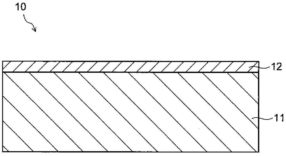
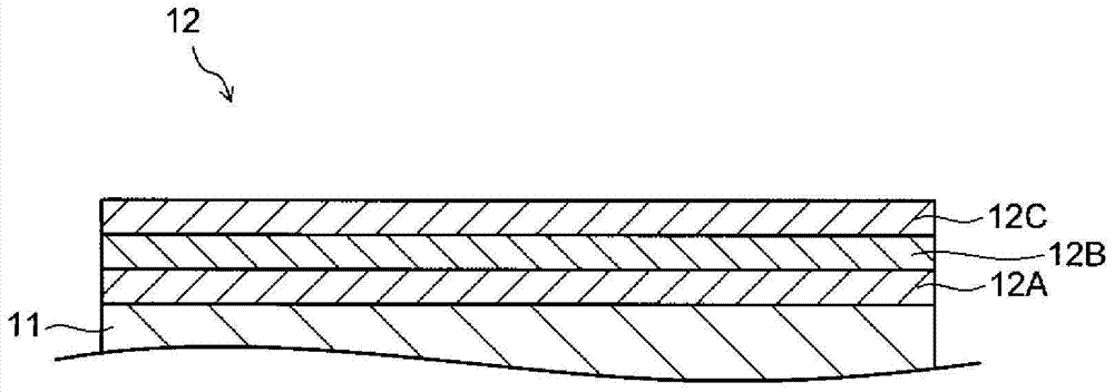
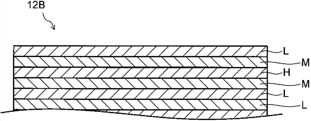
[0042] figure 1 It is a cross-sectional view of the near-infrared cut filter 10 (hereinafter referred to as IRCF10 ) of the first embodiment. figure 2 It is a cross-sectional view of the optical multilayer film 12 included in the IRCF10. image 3 is a cross-sectional view of the first SWPF portion 12B of the optical multilayer film 12 . Below, refer to Figure 1 ~ Figure 3 , illustrating the structure of IRCF10.
[0043] like figure 1 As shown, the IRCF 10 includes a transparent substrate 11 and an optical multilayer film 12 provided on at least one main surface of the transparent substrate 11 . In addition, the optical multilayer film 12 may be provided on one main surface of the transparent substrate 11 , or may be separately provided on each main surface of the transparent substrate 11 .
[0044] (transparent substrate 11)
[0045] The material of the transparent substrate 11 is not particularly limited as long as it can transmit light in at least the wavelength rang...
Embodiment 1
[0110] The optical multilayer film is composed of titanium oxide (high refractive index film), tantalum oxide (medium refractive index film), and silicon oxide (low refractive index film) (LMHML). In addition, the optical multilayer film has a passband with an average transmittance of 85% or more in the wavelength range of 400 to 700 nm, and an average transmittance of 10% or less in the wavelength range of 780 to 1000 nm on the near infrared side of the passband. The stop band of the region. Investigate the spectral characteristics of the optical multilayer film under the condition of 0° incidence by simulation. In the wavelength range of 400-700nm, there is no 2T at the position where the transmittance locally decreases by 5% or more. L / (T H +2T M ) of 100% (maximum), 0% (minimum), 70% of the film structure. 2T where there is no local decrease in the transmittance of the optical multilayer film by 5% or more L / (T H +2T M ) of 100% (maximum value), 0% (minimum value),...
Embodiment 2
[0115] The optical multilayer film has the same repeated lamination structure as in Example 1, except that it has a stop band in a region where the average transmittance is 10% or less in the wavelength range of 920 to 1170 nm on the near-infrared side of the above-mentioned pass band. . Investigate the spectral characteristics of the optical multilayer film under the condition of 0° incidence by simulation. In the wavelength range of 400-700nm, there is no 2T at the position where the transmittance locally decreases by 5% or more. L / (T H +2T M ) of 100% (maximum), 0% (minimum), 70% of the film structure. 2T where there is no local decrease in the transmittance of the optical multilayer film by 5% or more L / (T H +2T M ) of 100% (maximum value), 0% (minimum value), and 70% film structure are shown in Table 2 below. 2T L / (T H +2T M ) of 100% (maximum value) is 0.865, 0% (minimum value) is 0.807, and 70% is 0.847.
[0116] [Table 2]
[0117]
[0118] Figure 7 I...
PUM
| Property | Measurement | Unit |
|---|---|---|
| Plate thickness | aaaaa | aaaaa |
| Transmittance | aaaaa | aaaaa |
| Average transmittance | aaaaa | aaaaa |
Abstract
Description
Claims
Application Information