Method for reinforcing cutting edge of micro-cutting tool based on critical cutting thickness

A technology of cutting thickness and cutting edge, which is applied in the field of micro-tools, micro-tool edge strengthening based on critical cutting thickness, can solve the problems of inability to achieve segmented grinding, and achieve the goal of improving cutting conditions, facilitating implementation, and improving machining accuracy. Effect

Active Publication Date: 2014-12-17
SHANGHAI JIAO TONG UNIV +1
View PDF8 Cites 6 Cited by
  • Summary
  • Abstract
  • Description
  • Claims
  • Application Information

AI Technical Summary

Problems solved by technology

In the past, the control of cutting edge radius mainly relied on precision grinding, and segmental grinding could not be realized. In recent years, with the advancement of technology, the method of controlling the cutting edge blunt circle radius has become increasingly mature.

Method used


Image

  • Method for reinforcing cutting edge of micro-cutting tool based on critical cutting thickness
  • Method for reinforcing cutting edge of micro-cutting tool based on critical cutting thickness
  • Method for reinforcing cutting edge of micro-cutting tool based on critical cutting thickness

Examples


Embodiment Construction

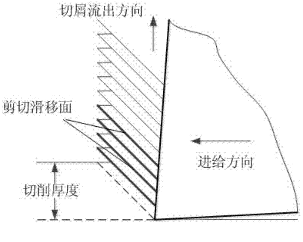
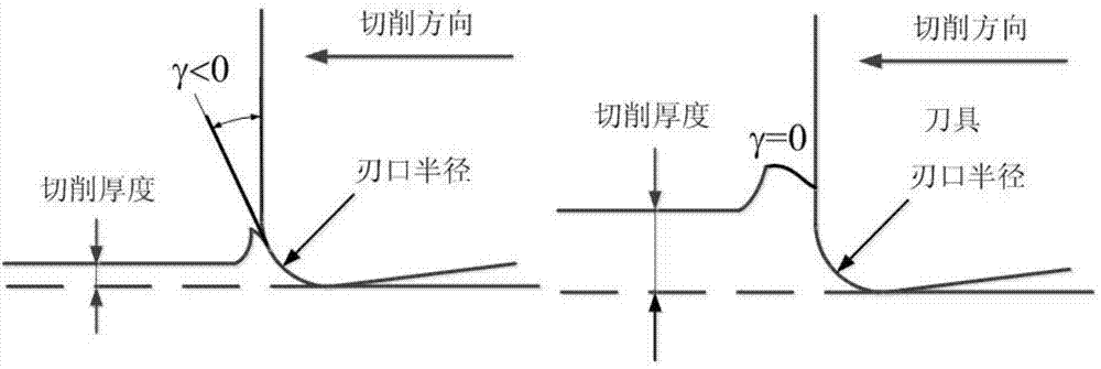
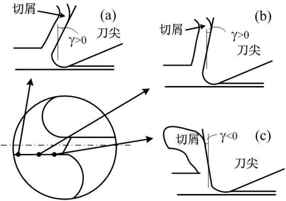
[0030] The invention relates to a cutting edge strengthening technology of a micro-knife, which can improve the cutting edge strength of the micro-knife, improve the cutting load distribution in the cutting edge area of ​​the micro-knife, improve the cutting state, and improve the cutting performance; it mainly relies on changing the cutting edge The blunt circle radius distribution of the area, and the change is based on the critical cutting thickness of the processed material and the processing conditions of the tool edge area, so that the cutting edge of the main cutting edge of the tool can be cut in the most reasonable situation .

[0031] The embodiments of the present invention are described in detail below in conjunction with the accompanying drawings. The following embodiments are based on the technical solutions of the present invention, providing detailed implementation and specific operating procedures, but the scope of protection of the present invention is not lim...


PUM

PropertyMeasurementUnit
Diameteraaaaaaaaaa

Abstract

The invention relates to a method for reinforcing a cutting edge of a micro-cutting tool based on critical cutting thickness. The method comprises the following steps of dividing a cutting edge area of the micro-cutting tool into a main edge outer edge area, an intermediate transitional area and a near transverse edge area, respectively determining and trimming the respective cutting-edge radii of the main edge outer edge area, the intermediate transitional area and the near transverse edge area according to the critical cutting thicknesses of different processed materials so as to reinforce the strength of the cutting edge and optimize the cutting performance. The method comprises the following steps: (1) determining the critical cutting thickness of a processed material through orthogonal cutting experiment or cutting finite element simulation; (2) dividing the cutting edge area of the micro-cutting tool into the main edge outer edge area, the intermediate transitional area and the near transverse edge area; (3) respectively determining respective cutting edge radii of the three areas according to the critical cutting thickness of the processed material; (4) trimming the cutting edges of the main edge outer edge area, the intermediate transitional area and the near transverse edge area in a micro-scale manner by utilizing a focus ion beam, and gradually trimming the cutting edge to the determined cutting edge radius. The method is feasible, the strength of the cutting edge is improved, the cutting state is improved, the service life of the cutting tool is prolonged, and the method is applicable to all micro-cutting tools.

Description

technical field [0001] The invention relates to a micro-tool for micro-machining, in particular to a micro-tool edge strengthening method based on a critical cutting thickness, and belongs to the technical field of micro-machining. Background technique [0002] Micro-miniature systems are a type of highly integrated optical, mechanical, electrical, hydraulic, magnetic, etc. systems within the micro-scale range. Micro-miniature structural parts are pure mechanical or electromechanical components that connect and support functional components, bear loads, perform motion or output power. One piece parts. Micro-scale structural parts have the following characteristics in terms of object scale, component materials and structural forms: (1) specifically refer to parts and structures whose overall scale is at the millimeter level and the characteristic scale is at the micron level; (2) are mainly composed of metals, alloys, metal-based Made of non-silicon materials such as composi...

Claims


Application Information

Patent Timeline
IPC IPC(8): B23B51/00B81C99/00
CPCB23B51/00B81C99/001
Inventor 陈明郑小虎魏莹莹于德栋董大鹏
Owner SHANGHAI JIAO TONG UNIV
Why Eureka
Try Eureka