
Machining method of stainless steel part with aluminum honeycomb core

A technology of parts processing and aluminum honeycomb, which is applied in the field of mechanical parts processing and manufacturing, can solve the problems of inability to complete the CNC machining of stainless steel aluminum honeycomb sandwich parts, the honeycomb structure does not allow the use of liquid coolant, and the bonding strength of the honeycomb sandwich structure is affected. Achieve the effect of avoiding thermal melting, improving cutting conditions, reducing yaw and chatter

Active Publication Date: 2020-04-24
CHENGDU AIRCRAFT INDUSTRY GROUP
View PDF15 Cites 1 Cited by
  • Summary
  • Abstract
  • Description
  • Claims
  • Application Information

AI Technical Summary

Problems solved by technology

At present, stainless steel aluminum honeycomb sandwich parts are usually composed of stainless steel plate, aluminum honeycomb sandwich core and aluminum plate from top to bottom. Due to the different cutting performance of different materials, the traditional milling method has been unable to complete the stainless steel aluminum honeycomb sandwich parts. CNC machining
The traditional method has the following disadvantages: First, the processing performance of different materials in the sandwich structure is not the same, and different tools need to be used for processing, and the honeycomb structure does not allow the use of liquid coolant, and a large amount of heat is generated during the cutting process, which will cause aluminum honeycomb Melting affects the bonding strength of the honeycomb sandwich structure at the same time; secondly, when processing different materials, the tool and cutting performance are inconsistent, and the parts are prone to deformation, which affects the quality of the parts. At the same time, the tool wears seriously during the processing, which increases the cost of parts processing

Method used


Image

  • Machining method of stainless steel part with aluminum honeycomb core

Examples


Embodiment 1

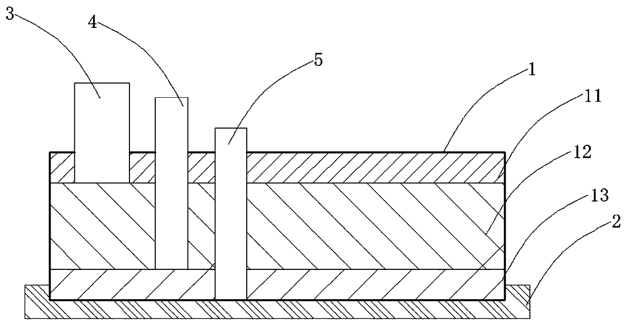
[0026] The main structure of this embodiment, such as figure 1 Shown, a kind of stainless steel aluminum honeycomb sandwich part processing method comprises the following steps:

[0027] (1) Install the part body on the machine tool table through the positioning fixture, make the lower surface of the part body fit the upper surface of the positioning fixture, and the plane where it is fitted is used as the clamping positioning surface;

[0028] (2) In the process of using CNC to process the part body, different milling cutters are used respectively based on the clamping positioning surface, and the milling process is carried out in layers for different materials in the part body in turn. All milling cutters are milled by trochoidal milling milling of the part body;

[0029] (3) After the milling of the part body is completed, remove the burrs after processing the part body, thereby completing the processing of the entire part body.

[0030] The specific implementation is tha...

Embodiment 2

[0033] On the basis of the above-mentioned embodiments, this embodiment further defines the structure of the part body 1, such as figure 1 As shown, the part body 1 is composed of the upper stainless steel layer 11, the middle aluminum honeycomb layer 12, and the lower aluminum plate layer 13. When the part body 1 is fixed on the machine tool workbench by the positioning fixture 2, the aluminum plate layer 11 in the part body 1 The lower surface of the lower surface is bonded with the upper surface of the positioning fixture 2, and the bonding surface is the clamping positioning surface. Other parts of this embodiment are the same as those of the foregoing embodiment, and will not be repeated here.

Embodiment 3

[0035] On the basis of the foregoing embodiments, this embodiment further limits the number of milling cutters, such as figure 1 As shown, the stainless steel layer 11 of the part body 1 is milled by the first milling cutter 3, the aluminum honeycomb layer 12 is milled by the second milling cutter 4, and the aluminum plate layer 13 is milled by the third milling cutter 5; the first milling The tool paths of the cutter 3, the second milling cutter 4, and the third milling cutter 5 are identical, and the diameter of the first milling cutter 3 is greater than the diameters of the second milling cutter 4 and the third milling cutter 5, and the diameter of the second milling cutter 4 is different. Less than the diameter of the third milling cutter 5. Obtain the cycloidal milling cutter track of the part processing position through software tools, select the processing tool of stainless steel material for processing, and in the process of processing the stainless steel plate layer, en...


PUM


Abstract

The invention discloses a machining method of a stainless steel part an aluminum honeycomb core. The method comprises the following steps that 1) a part body is mounted on a machine tool workbench through a positioning clamp, the lower surface of the part body is fitted to the upper surface of the positioning clamp, and the fitted plane is taken as a clamping positioning surface; (2) in the process of numerical control machining of the part body, different milling cutters are used for milling different materials in the part body layer by layer, and the milling cutters all carry out cycloid milling; and 3) after milling is completed, burrs are removed, and machining is completed. According to the method, by means of layered machining, it can be guaranteed that the different cutters are usedfor the different materials in a sandwich structure during part machining, and the machining quality is guaranteed; under the condition that fluid cooling liquid cannot be used, cuttings can be automatically taken away in a cycloid milling mode, cooling is sufficient, heat dissipation is guaranteed, conditions are improved, deflection and flutter of the cutters can be reduced, the cutting force is stable, and the service life of the tools is prolonged; and due to effective diffusion of cutting heat, the machining quality and efficiency of parts are improved.

Description

technical field [0001] The invention relates to the technical field of machining and manufacturing of mechanical parts, in particular to a method for processing stainless steel aluminum honeycomb sandwich parts. Background technique [0002] With the development of aviation technology, the requirements of the new generation of aviation equipment are getting higher and higher. The stainless steel aluminum honeycomb sandwich structure has been widely used for its outstanding properties such as light weight, high specific stiffness, high specific strength, high surface finish, and corrosion resistance. As an integral part of the new generation of aviation equipment, stainless steel aluminum honeycomb sandwich parts play a vital role in the development of the entire aviation equipment. At present, stainless steel aluminum honeycomb sandwich parts are usually composed of stainless steel plate, aluminum honeycomb sandwich core and aluminum plate from top to bottom. Due to the diff...

Claims


Application Information

Patent Timeline
Patent Type & Authority Applications(China)
IPC IPC(8): B23C3/00B23Q3/06
CPCB23C3/00B23Q3/06
Inventor 周进王鹏程曹虎周文昌
Owner CHENGDU AIRCRAFT INDUSTRY GROUP
Learn More