Electrohydraulic control reserving valve and electrohydraulic control system

An electro-hydraulic control system and electro-hydraulic control technology, applied in the direction of fluid pressure actuators, servo motors, servo motor components, etc., can solve the problem of small flow rate of reversing valves

Active Publication Date: 2014-12-17
WUHAN MARINE MACHINERY PLANT
View PDF6 Cites 1 Cited by
  • Summary
  • Abstract
  • Description
  • Claims
  • Application Information

AI Technical Summary

Problems solved by technology

[0004] In order to solve the problem of small flow rate of the electro-hydraulic control reversing valve in the prior art, the embodiment of the present invention provides an electro-hydraulic control reversing valve and an electro-hydraulic control system

Method used


Image

  • Electrohydraulic control reserving valve and electrohydraulic control system
  • Electrohydraulic control reserving valve and electrohydraulic control system
  • Electrohydraulic control reserving valve and electrohydraulic control system

Examples


Embodiment 1

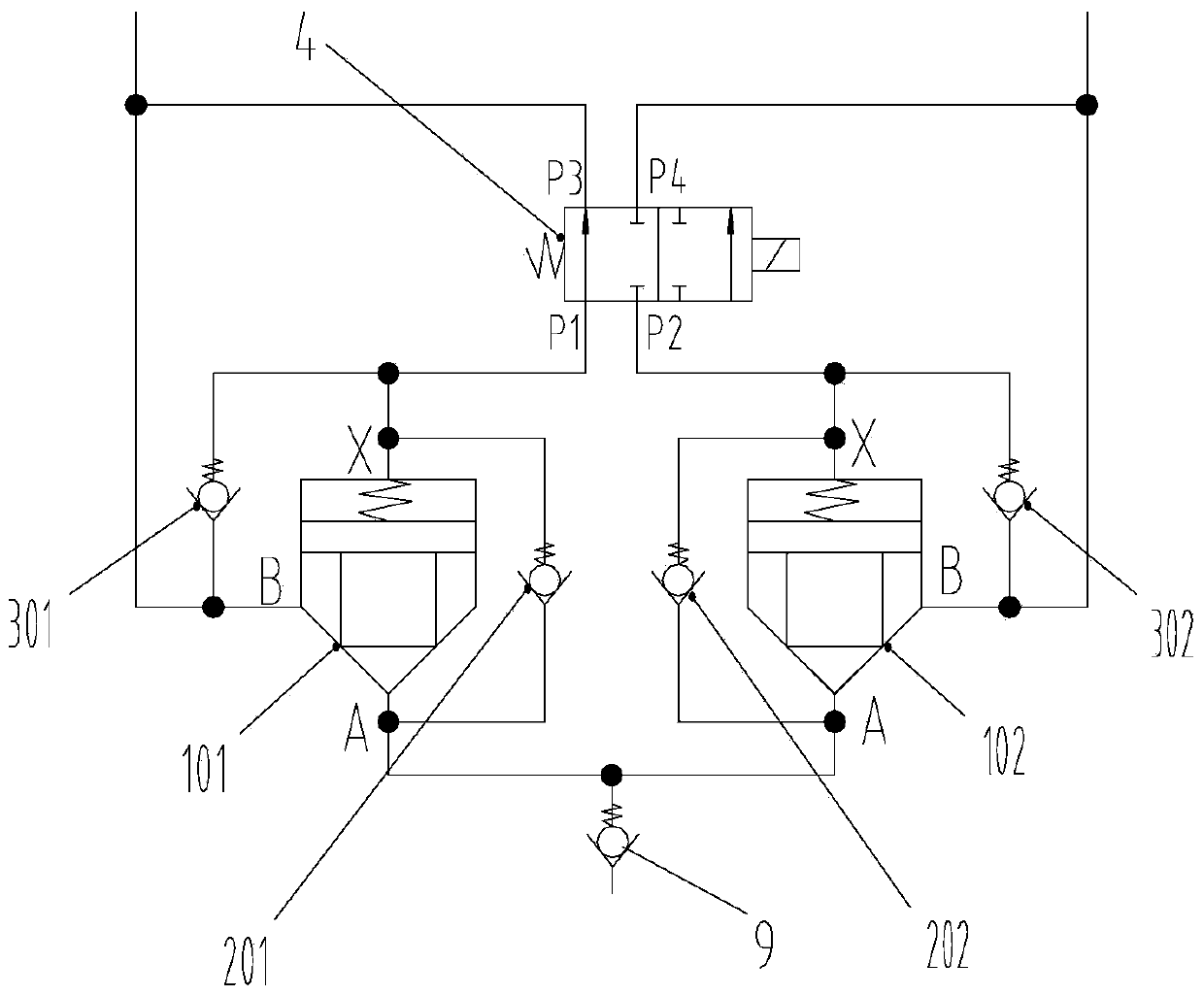
[0025] The embodiment of the present invention provides an electro-hydraulic control reversing valve, such as figure 1 As shown, the electro-hydraulic control reversing valve includes: a first cartridge valve 101, a second cartridge valve 102 and a two-position four-way electromagnetic reversing valve 4, the A port of the first cartridge valve 101 and the second cartridge valve The A port of the valve 102 is connected, the X port of the first cartridge valve 101 is connected with the P1 port of the two-position four-way electromagnetic reversing valve 4, the X port of the second cartridge valve 102 is connected with the two-position four-way electromagnetic reversing valve 4 The P2 port of the two-position four-way electromagnetic reversing valve 4 communicates with the B port of the first cartridge valve 101 and the first actuator (not shown in the figure), and the two-position four-way electromagnetic reversing valve 4 Port P4 of the second cartridge valve 102 communicates w...

Embodiment 2

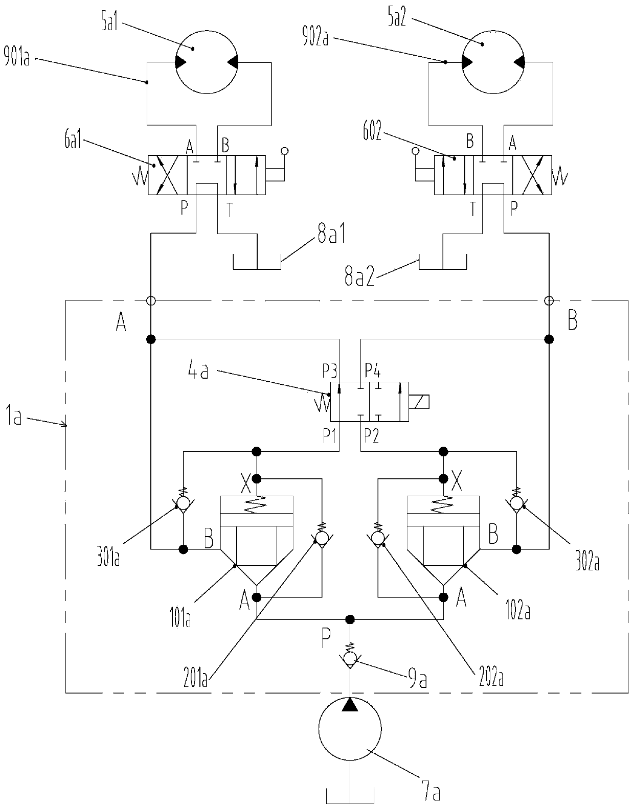
[0032] The embodiment of the present invention provides an electro-hydraulic control system, such as figure 2 As shown, the system includes: the electro-hydraulic control reversing valve 1a provided in Embodiment 1, the hydraulic pump 7a and at least two actuators, the oil outlet of the hydraulic pump 7a communicates with the P port of the electro-hydraulic control reversing valve 1a, The electro-hydraulic control reversing valve 1a includes: a first cartridge valve 101a, a second cartridge valve 102a and a two-position four-way electromagnetic reversing valve 4a, the port A of the first cartridge valve 101a and the port A of the second cartridge valve 102a Port A is connected and communicated with the P port of the electro-hydraulic control reversing valve 1a, the X port of the first cartridge valve 101a is connected with the P1 port of the two-position four-way electromagnetic reversing valve 4a, and the X port of the second cartridge valve 102a It communicates with the P2 ...

Embodiment 3

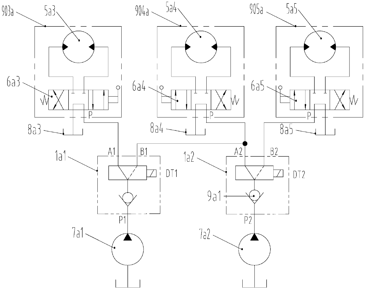
[0045] The embodiment of the present invention provides another electro-hydraulic control system. Compared with the second embodiment, this embodiment is equipped with two hydraulic pumps, three actuators and two electro-hydraulic control reversing valves.

[0046] Such as image 3 As shown, when there are three actuators and they are respectively the third actuator 903a, the fourth actuator 904a and the fifth actuator 905a, there are two hydraulic pumps and they are respectively the first hydraulic pump 7a1 and the second hydraulic pump 7a2 , there are two electro-hydraulic control reversing valves, which are respectively the first electro-hydraulic control reversing valve 1a1 and the second electro-hydraulic control reversing valve 1a2, the third actuator 903a includes a motor 5a3 and a manual reversing valve 6a3, and the manual reversing valve The A port of the directional valve 6a3 is connected with the A port of the motor 5a3, the B port of the manual directional valve 6a...


PUM


Abstract

The invention discloses an electrohydraulic control reversing valve and an electrohydraulic control system and belongs to the field of hydraulic valves. The electrohydraulic control reserving valve comprises a first cartridge valve, a second cartridge valve and a two-position four-way electromagnetic directional valve, wherein a port A of the first cartridge valve is communicated with a port A of the second cartridge valve; a port X of the first cartridge valve is communicated with a port P1 of the two-position four-way electromagnetic directional valve; a port X of the second cartridge valve is communicated with a port P2 of the two-position four-way electromagnetic directional valve; a port P3 of the two-position four-way electromagnetic directional valve and a port B of the first cartridge valve are communicated with a first actuating mechanism; the two-position four-way electromagnetic directional valve is communicated with the first actuating mechanism; a port B of the two-position four-way electromagnetic directional valve is communicated with a second actuating mechanism. The electrohydraulic control system comprises the electrohydraulic control reversing valve, a hydraulic pump and an actuating mechanism, wherein the electrohydraulic control reversing valve comprises the cartridge valves and the two-position four-way electromagnetic directional valve, so that the electrohydraulic control reversing valve has relatively high flow capacity.

Description

technical field [0001] The invention relates to the field of hydraulic valve parts, in particular to an electro-hydraulic control reversing valve and an electro-hydraulic control system. Background technique [0002] The existing electro-hydraulic control directional valve is a combination of an electromagnetic directional valve and a hydraulic control directional valve. The electro-hydraulic control directional valve is connected between the hydraulic pump and the actuator, and is used to change the hydraulic oil provided by the hydraulic pump. The flow direction allows the hydraulic oil to flow into the actuator, thereby controlling the work of the actuator. [0003] At present, in the hydraulic system of deck machinery, the maximum flow rate of each hydraulic pump can be as high as 4000L / min, while the maximum flow rate of the existing electro-hydraulic control reversing valve does not exceed 500L / min, making the existing electro-hydraulic control reversing valve Directi...

Claims


Application Information

Patent Timeline
Patent Type & Authority Applications(China)
IPC IPC(8): F15B13/02F15B11/00
Inventor 吴建磊方敏胡发国司小冬程源
Owner WUHAN MARINE MACHINERY PLANT
Why Eureka
Try Eureka