
Constant-flow drain valve

A technology of drain valve and water valve, applied in valve details, valve device, valve shell structure, etc., can solve problems such as difficult closing, high maintenance cost, and inability to remove oil and water waste liquids in a timely and effective manner.

Active Publication Date: 2014-12-17
DONGGUAN SHANTIAN PRECISION MACHINERY
View PDF7 Cites 5 Cited by
  • Summary
  • Abstract
  • Description
  • Claims
  • Application Information

AI Technical Summary

Problems solved by technology

[0002] The existing drain valves on the market have the following deficiencies. One: the design is unreasonable, often jammed, the gas cannot be closed, the gas is easy to leak, and the repair is not good. Only the drain valve needs to be replaced, resulting in high maintenance costs; Two: Due to the pushing and extrusion effect of airflow discharge, it is difficult to close after draining, and the startup or closing time is delayed a lot, resulting in low work efficiency; Third: The drain valve is a floating ball to open the piston, and the piston is made of rubber , Rubber seals are easy to deform frequently, affecting their sealing performance, prone to air leakage, poor quality, and short service life
And there are two kinds of discharge methods for existing drain valves, the first is fast drainage, and it is closed when it is released; the second is intermittent discharge. Faults occur, shortening the service life of the parts

Method used


Image

  • Constant-flow drain valve

Examples


Embodiment Construction

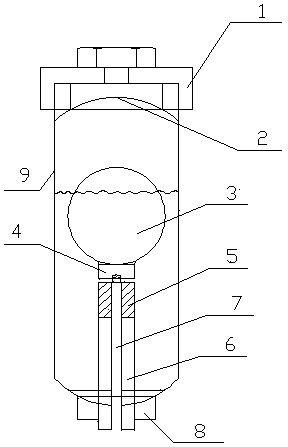
[0011] In this example, refer to figure 1 As shown, a flow equalizing drainage valve includes a water valve cavity 9, a water valve inlet connector 1 installed on the upper end of the water valve cavity 9, and a filter screen 2 arranged in the water valve inlet connector 1 , and the water valve drain connector 8 installed at the lower end of the water valve cavity 9, the water valve outlet 6 arranged on the water valve drain connector 8, and the valve pipe 5 arranged on the water valve outlet 6 , and the spool 7 movably inserted in the center of the valve tube 5 , the plunger valve 4 arranged on the top of the spool 7 , and the float 3 arranged on the plunger valve 4 .

[0012] Wherein, the diameter of the floating ball 3 is smaller than the inner diameter of the water valve cavity 9, and the floating ball 3 moves along with the rise and fall of the water level in the water valve cavity 9 without the friction of the water valve cavity 9, and the water level in the water valve ...


PUM


Abstract

The invention discloses a constant-flow drain valve which comprises a water valve cavity, a water valve water inlet connector, a filter screen, a water valve drain connector, a water valve liquid outlet, a valve pipe, a valve column, a plunger valve and a floating ball. The water valve water inlet connector is arranged at the upper end of the water valve cavity, the filter screen is arranged in the water valve water inlet connector, the water valve drain connector is arranged at the lower end of the water valve cavity, the water valve liquid outlet is formed in the water valve drain connector, the valve pipe is arranged on the water valve liquid outlet, the valve column movably penetrates into the center of the valve pipe, the plunger valve is arranged at the top of the valve column, and the floating ball is arranged on the plunger valve. The plunger valve is lifted directly through the buoyancy of the floating ball, the buoyancy of the floating ball and opening of the plunger valve are in direct proportion, opening of the plunger valve, the open area of the valve column and the valve pipe and the drain amount of the valve column and the valve pipe reach a balance point, water can be drained automatically and stably, water outlet flow is constant, the design is simple, jamming is reduced, air leakage is avoided, observation and detection are facilitated, and the constant-flow drain valve can be used for experiment detection, and is simple in structure, convenient to main, low in maintenance cost, high in sealing performance, long in service life, and high in work efficiency.

Description

technical field [0001] The invention relates to a drain valve, in particular to an equal-flow drain valve used in air compressor dryers, compressed air systems, and various oil-water waste liquids that need to be discharged. Background technique [0002] The existing drain valves on the market have the following deficiencies. One: the design is unreasonable, often jammed, the gas cannot be closed, the gas is easy to leak, and the repair is not good. Only the drain valve needs to be replaced, resulting in high maintenance costs; Two: Due to the pushing and extrusion effect of airflow discharge, it is difficult to close after draining, and the startup or closing time is delayed a lot, resulting in low work efficiency; Third: The drain valve is a floating ball to open the piston, and the piston is made of rubber , Rubber seals are easy to deform frequently, affecting their sealing performance, prone to air leakage, poor quality, and short service life. And there are two kinds ...

Claims


Application Information

Patent Timeline
IPC IPC(8): F16K31/30
CPCF16K27/041F16K31/30F16K33/00
Inventor 任文建
Owner DONGGUAN SHANTIAN PRECISION MACHINERY
Learn More