Anti-washing throttle valve sealing surface structure

A technology of sealing surface and throttle valve, which is applied in the direction of valve details, valve device, valve element and valve seat, etc. It can solve the problems of large front and rear pressure difference, high working pressure, internal leakage, etc., and achieve a solution Washout and inclusion effects

Inactive Publication Date: 2014-12-17
ZHANGJIAKOU POWER GENERATION FACTORY OF DATANG INT POWER GENERATION
View PDF0 Cites 2 Cited by
  • Summary
  • Abstract
  • Description
  • Claims
  • Application Information

AI Technical Summary

Problems solved by technology

[0002] The high and low pressure bypass steam conversion valve (a throttle valve) in power plants has high working pressure and large pressure difference between front and back, and has high requirements for tightness. Imported valves are mostly used, and some domestic valves with foreign technology are used. Zhangjiakou Power Plant The high and low bypass pressure reducing valve of No. 5 unit is produced by Harbin Valve Co., Ltd. with German technology. It is found that the internal leakage is serious during use. It often occurs after one use after maintenance. Although there are many impurities in the steam-water system, However, the valve structure design is the main reason. In order to reduce the erosion of the steam flow on the sealing surface, it adopts the structure of placing the valve cage in the valve seat to adjust the flow rate. Although this can avoid the erosion of the sealing surface, the cleanliness of the steam There are very high requirements on the precision, and impurities such as welding slag larger than 2.5mm are not allowed, otherwise the impurities will be stuck in the sealing surface when the valve is closed, resulting in internal leakage

Method used


Image

  • Anti-washing throttle valve sealing surface structure

Examples


Embodiment Construction

[0007] In order to better understand the technical solutions of the present invention, the embodiments provided by the present invention will be described in detail below in conjunction with the accompanying drawings.

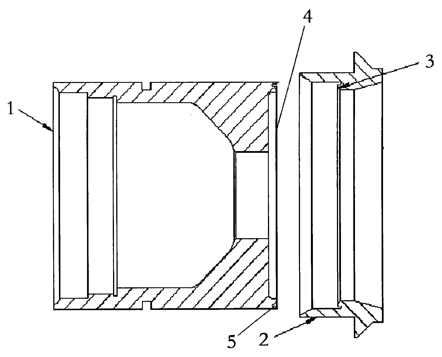
[0008] An embodiment of the present invention provides a sealing surface structure of an anti-scouring throttle valve, including: a valve clack 1, a valve cage 2, and a valve seat. On the inner wall of the valve cage 2; the upper surface of the valve flap 1 is the valve flap sealing surface 4, and a shroud 5 is arranged on the circumference of the valve flap sealing surface 4 to prevent fluid erosion. The distance between the disc 1 and the cage 2 or the depth of the disc 1 inserted into the cage 2 is used to control the flow area, and the valve is completely closed by the close contact between the sealing surface 4 of the disc and the sealing surface 5 of the valve seat. Made of wear-resistant alloy.

[0009] The above description is only the preferred embodi...


PUM


Abstract

The invention discloses an anti-washing throttle valve sealing surface structure. The anti-washing throttle valve sealing surface structure comprises a valve clack, a valve cage and a valve seat, wherein the valve cage and the valve seat are of an integrated structure; a sealing surface of the valve seat is arranged on an inner wall of the valve cage; the upper surface of the valve clack is a valve clack sealing surface and a shroud band is arranged at the circumference of the valve clack sealing surface to prevent fluid from washing. The flowing area is controlled according to the distance between the valve clack and the valve cage or the depth of inserting the valve clack into the valve cage; the valve is completely closed by the tight contact of the valve clack sealing surface and the sealing surface of the valve seat; the two sealing surfaces are made of anti-wearing alloys. The valve cage is arranged on the structure outside the valve clack so that impurities are prevented from being clamped in the sealing surfaces; the anti-washing shroud band of the valve clack sealing surface is designed in order to prevent the valve clack sealing surface from being washed by the fluid; the valve clack sealing surface is arranged in the anti-washing shroud band; meanwhile, the valve clack sealing surface does not have a washing angle so that the problems of sealing surface washing and impurity carrying are effectively solved.

Description

technical field [0001] The invention relates to the technical field of high and low pressure bypass steam conversion valves in power plants, in particular to a sealing surface structure of an anti-scouring throttle valve. Background technique [0002] The high and low pressure bypass steam conversion valve (a throttle valve) in power plants has high working pressure and large pressure difference between front and back, and has high requirements for tightness. Imported valves are mostly used, and some domestic valves with foreign technology are used. Zhangjiakou Power Plant The high and low bypass pressure reducing valve of No. 5 unit is produced by Harbin Valve Co., Ltd. with German technology. It is found that the internal leakage is serious during use. It often occurs after one use after maintenance. Although there are many impurities in the steam-water system, However, the valve structure design is the main reason. In order to reduce the erosion of the steam flow on the s...

Claims


Application Information

Patent Timeline
Patent Type & Authority Applications(China)
IPC IPC(8): F16K51/00
CPCF16K25/00
Inventor 闫青石勇王东黎刘博付晓升赵利宣任立军张永斌
Owner ZHANGJIAKOU POWER GENERATION FACTORY OF DATANG INT POWER GENERATION
Why Eureka
Try Eureka