Automatic defrosting system for medical refrigerators

A refrigerator, automatic technology, applied in defrosting, household refrigeration devices, applications, etc., can solve the problems of deviating from the refrigeration target temperature and failing to achieve the effect of defrosting, and achieve the effect of improving preservation quality and maintaining temperature

Active Publication Date: 2016-05-25
WANSHENG PRECISION MACHINERY JIANGSU
View PDF7 Cites 0 Cited by
  • Summary
  • Abstract
  • Description
  • Claims
  • Application Information

AI Technical Summary

Problems solved by technology

[0004] Since automatic defrosting is realized by turning on the heater at the right time to heat the frosted evaporator, although the most reasonable cut-in and exit time can be controlled through a series of methods, the actual temperature in the box will vary over a period of time. Deviation from cooling target temperature is inevitable
For medical refrigerators with stricter temperature control, if the automatic defrosting time is too short, the defrosting effect will not be achieved, and if the time is too long, the temperature alarm system will be triggered. How to provide a method suitable for medical refrigerators The automatic defrosting system is a technical problem to be solved in this field

Method used


Image

  • Automatic defrosting system for medical refrigerators

Examples


Embodiment 1)

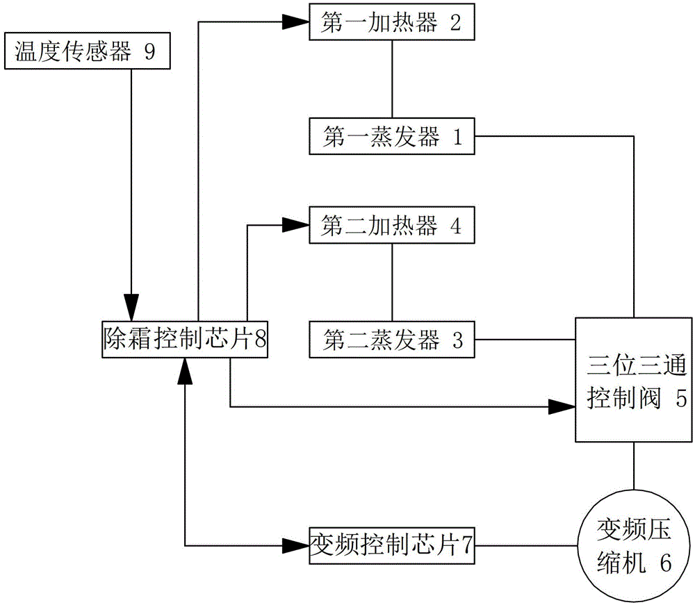
[0022] See figure 1 , the automatic defrosting system of the medical refrigerator of this embodiment includes a first evaporator 1, a first heater 2 arranged on the first evaporator 1, a second evaporator 3, and a second evaporator 3 arranged on the second evaporator 3. The second heater 4, the three-position three-way control valve 5, the frequency conversion compressor 6, the frequency conversion control chip 7 for controlling the working frequency of the frequency conversion compressor, the temperature sensor 9 for real-time detection of the temperature in the box and the control start Defrost control chip 8 for defrosting and ending defrosting. The signal end of the temperature sensor 9 is connected with the signal end of the defrosting control chip 8 . The signal terminals of the defrosting control chip 8 are respectively connected with the control terminals of the first heater 2 , the second heater 4 and the three-position three-way control valve 5 , and the signal term...

Embodiment 2)

[0032] The rest of this embodiment is the same as Embodiment 1, the difference is: the first operating frequency f of the compressor in this embodiment 1 25Hz, T 1 is 3.2°C, so the second operating frequency of the compressor is f 2 is 41.6Hz.

Embodiment 3)

[0034] The rest of this embodiment is the same as Embodiment 1, the difference is: the first operating frequency f of the compressor in this embodiment 1 25Hz, T 1 is 3.8°C, so the second operating frequency of the compressor is f 2 is 46.4Hz.


PUM


Abstract

The invention relates to an automatic defrosting system of a medical cold closet. The automatic defrosting system of the medical cold closet comprises a temperature sensor and a defrosting control chip, wherein the signal end of the temperature sensor is connected with the signal end of the defrosting control chip. The automatic defrosting system further comprises a first evaporator, a first heater arranged on the first evaporator, a second evaporator, a second heater arranged on the second evaporator, a three-position three-way control valve, an inverter compressor and an inverter control chip used for controlling the working frequency of the inverter compressor. An outlet of the inverter compressor is connected with an inlet of the three-position three-way control valve, and two outlets of the three-position three-way control valve are connected with the first evaporator and the second evaporator respectively. The signal end of the deforesting control chip is connected with the control end of the first heater, the control end of the second heater, the control end of the three-position three-way control valve and the signal end of the inverter control chip. The automatic defrosting system of the medical cold closet can compensate for the loss of cooling capacity when conducting deforesting, and the temperature in the closet is made to fluctuate within a very small temperature range when deforesting is conducted.

Description

technical field [0001] The invention relates to a component of a refrigeration system of a medical refrigerator. Background technique [0002] Medical refrigerators are professional equipment used by blood banks, hospitals and the Center for Disease Control and Prevention to refrigerate blood, and can also be used to refrigerate pharmaceutical reagents and biological products. Because medical refrigerators have high requirements for controlling the refrigeration temperature, general medical refrigerators use high-precision temperature control chips to collect the temperature in the box. If the deviation between the temperature and the refrigeration target temperature reaches a certain preset value, the temperature The control chip will send instructions to the refrigeration components to turn on or off the refrigeration circuit, thereby controlling the temperature rise and fall, and ensuring that the refrigeration temperature fluctuates within a small range. However, the fr...

Claims


Application Information

Patent Timeline
Patent Type & Authority Patents(China)
IPC IPC(8): F25D21/08F25D29/00
Inventor 万建军
Owner WANSHENG PRECISION MACHINERY JIANGSU
Why Eureka
Try Eureka