Freezer hot fluorine defrosting machine

A thermal fluoride froster and cold storage technology, applied in the field of cold storage systems, can solve the problems of affecting the refrigeration effect of the evaporator, reducing the refrigeration efficiency of the evaporator, and failing to make full use of energy, etc. Energy saving effect

Inactive Publication Date: 2014-12-17
苏州新亚科技有限公司
View PDF3 Cites 3 Cited by
  • Summary
  • Abstract
  • Description
  • Claims
  • Application Information

AI Technical Summary

Problems solved by technology

[0002] Now the cold storage is getting bigger and bigger, and there are more and more evaporators in the cold storage. Often, multiple groups of evaporators are arranged to form the refrigeration and evaporation system of the entire cold storage. The thicker it is, the cooling effect of the evaporator is affected and the cooling efficiency of the evaporator is reduced, so it is necessary to defrost the evaporator in time
[0003] At present, the method of defrosting mainly adopts electric heating or thermal auxiliary. The electric heating method is external heating, and the defrosting speed is slow. It is more reasonable to use hot fluorine; Widely used in refrigeration and ice-making industries, the use of hot fluorine defrosting technology can improve production efficiency, save labor and reduce energy consumption, but the hot fluorine defrosting technology currently on the market still has the following defects: Fluorine defrosting is for all evaporators, and refrigeration cannot be performed at the same time as defrosting; the refrigerant after defrosting directly enters the compressor, which cannot make full use of energy; manual control of the opening and closing of valves is required, which is highly dependent on workers

Method used


Image

  • Freezer hot fluorine defrosting machine
  • Freezer hot fluorine defrosting machine
  • Freezer hot fluorine defrosting machine

Examples


Embodiment

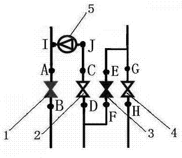
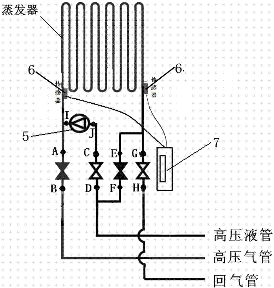
[0029] Such as Figure 1-3 A thermal fluorine defrosting device for cold storage shown includes: a first control valve 1 , a second control valve 2 , a third control valve 3 , a fourth control valve 4 , an expansion valve 5 and a controller.

[0030] The connection relationship of the hot fluorine defrosting device of the cold storage is as follows: the B end of the first control valve 1 is connected with the high-pressure air pipe, and the A end is connected with the inlet of the evaporator; the D end of the second control valve 2 is connected with the high-pressure liquid Pipe connection, the C end is connected with the J end of the expansion valve 5, the I end of the expansion valve 5 is connected with the inlet of the evaporator; the G end of the fourth control valve 4 is connected with the evaporator outlet, and the H end is connected with the return air pipe; The E end of the third control valve 3 is connected to the outlet of the evaporator, and the F end is connected t...


PUM


Abstract

The invention discloses a freezer hot fluorine defrosting machine, which comprises a first control valve, a second control valve, a third control valve and a fourth control valve, wherein the end D of the second control valve is connected with a high pressure liquid pipe, the end C of the second control valve is connected with the end J of an expansion valve, the end I of the expansion valve is connected with an inlet of an evaporator, the end G of the fourth control valve is connected with an outlet of the evaporator, the end H of the fourth control valve is connected with an air return pipe, the end B of the first control valve is connected with a high pressure air pipe, the end A of the first control valve is connected with one end of the evaporator, the end E of the third control valve is connected with the other end of the evaporator, and the end F of the third control valve is connected with the high pressure liquid pipe. The defrosting device has the advantages that the heat generated by a compressor is used for defrosting, the energy consumption of defrosting is decreased, and the consumption of energy source is decreased; during defrosting, the high pressure gas is condensed to provide a refrigerant for the subsequent refrigerating of the evaporator, and the energy consumption is further saved; the defrosting is performed from interior to exterior, and the defrosting speed is high.

Description

technical field [0001] The invention relates to a defrosting system in a cold storage, in particular to a thermal fluorinated defrosting device for a cold storage and a cold storage system using the thermal fluorinated defrosting device for the cold storage. Background technique [0002] Now the cold storage is getting bigger and bigger, and there are more and more evaporators in the cold storage. Often, multiple groups of evaporators are arranged to form the refrigeration and evaporation system of the entire cold storage. The thicker it is, the cooling effect of the evaporator is affected and the cooling efficiency of the evaporator is reduced, so it is necessary to defrost the evaporator in time. [0003] At present, the method of defrosting mainly adopts electric heating or thermal auxiliary. The electric heating method is external heating, and the defrosting speed is slow. It is more reasonable to use hot fluorine; Widely used in refrigeration and ice-making industries,...

Claims


Application Information

Patent Timeline
Patent Type & Authority Applications(China)
IPC IPC(8): F25D21/12F25D29/00
Inventor 闻建中
Owner 苏州新亚科技有限公司
Why Eureka
Try Eureka