
Power supply path tracking method suitable for large-scale complex power distribution network
A technology of power supply path and distribution network, applied in data processing applications, electrical digital data processing, special data processing applications, etc., can solve problems such as inability to meet real-time control and slow response speed
- Summary
- Abstract
- Description
- Claims
- Application Information
AI Technical Summary
Problems solved by technology
Method used
Image

Examples
Embodiment
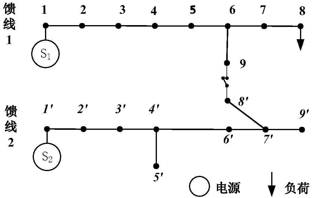
[0024] Taking a small power system model as an example below, a specific embodiment of the present invention is introduced. The grid model of this embodiment is as follows figure 1 As shown, there are two feeders in the grid model, feeder 1 and feeder 2, where feeder 1 includes 9 nodes 1, 2, 3, 4, 5, 6, 7, 8, 9, and feeder 2 includes 9 nodes 1 `, 2`, 3`, 4`, 5`, 6`, 7`, 8`, 9`, where nodes 1 and 1` are power supply mounting nodes, two power supplies S 1 , S 2 Both are active, there is a tie switch between nodes 9 and 8`, and the target device is the load Load mounted on node 8 of feeder 1. In this embodiment, the tie switch between nodes 9 and 8` is respectively shown to be closed and opened The power supply path tracing method for two cases.
[0025] This embodiment includes the following steps:
[0026] 1) Establish a distribution network model: Put the active power supplies in the distribution network into the set Source, and the i-th power supply S in the set Source i ...
PUM
 Abstract
Description
Claims
Application Information