Contact spring and brush contact element applying same

A technology of contact reeds and contacts, applied in the direction of electrical components, circuits, connections, etc., can solve problems such as waste of materials, rising costs, failure of electrical connectors, etc., and achieve the effect of improving transmission power

Inactive Publication Date: 2014-12-17
CHINA AVIATION OPTICAL-ELECTRICAL TECH CO LTD
View PDF6 Cites 12 Cited by
  • Summary
  • Abstract
  • Description
  • Claims
  • Application Information

AI Technical Summary

Problems solved by technology

[0003] The above-mentioned brush contacts and electric slip rings have been widely used in rotary electrical connectors, but when the electric slip ring is used to transmit high power (current greater than 200A), due to the single brush contact of the above structure The power of components and electric slip rings is limited, so it is necessary to use multiple parallel connections to transmit power together. However, due to the influence of machining, assembly and other factors, the actual power of each transmission line is not the same. In this case, when When the design power redundancy of brush contacts and electric slip rings is small, individual paths may burn out due to the difference in actual transmission power, resulting in failure of the entire electrical connector; when the power design redundancy is large , it is necessary to increase the axial dimension of the electrical connector accordingly. In this way, a lot of material will be wasted, and the cost of the product will also increase accordingly.

Method used


Image

  • Contact spring and brush contact element applying same
  • Contact spring and brush contact element applying same
  • Contact spring and brush contact element applying same

Examples


Embodiment Construction

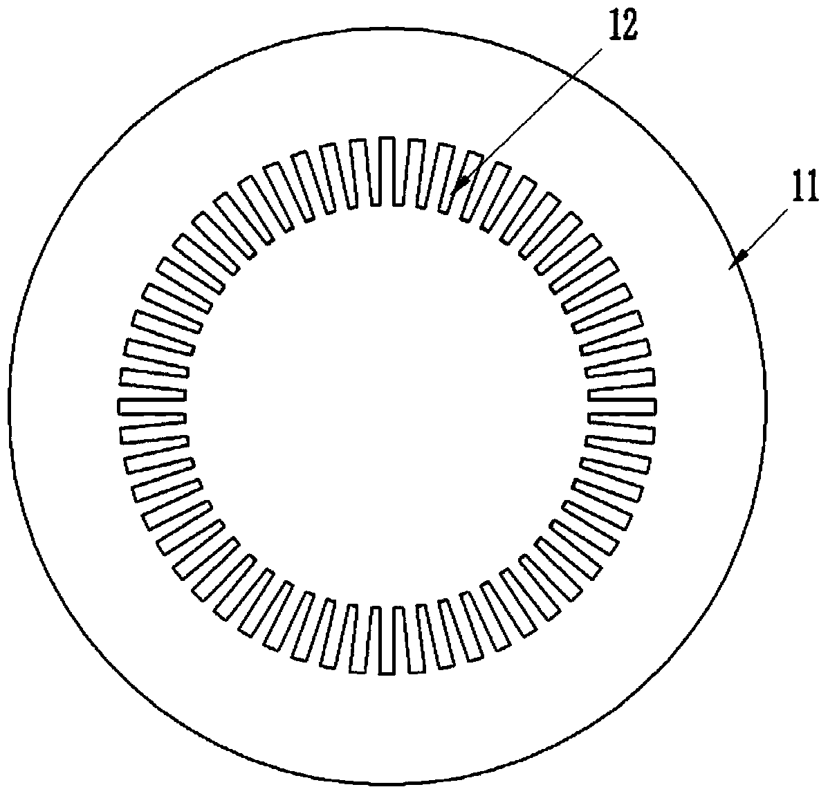
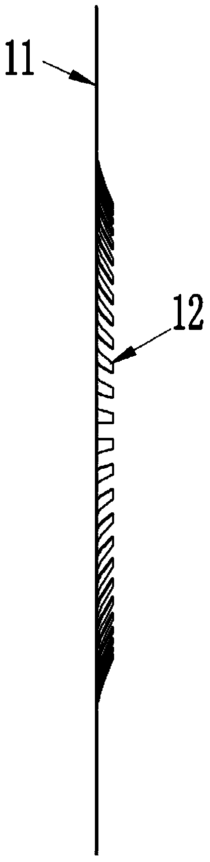
[0020] Examples of contact reeds, such as Figure 1-2 As shown, the contact reed includes a female ring 11. In this embodiment, the female ring 11 is a circular ring made of copper, and a cantilevered elastic contact finger 12 is arranged inside it. The elastic contact finger 12 wraps around the female ring 11. The center line of the center line is evenly arranged. In this embodiment, the elastic contact fingers 12 and the female ring 11 are of an integrated structure, which is formed by punching. Each elastic contact finger 12 includes a fixed end located on the female ring 11 and gradually The contact end close to the center line of the female ring, the contact end of the elastic contact finger 12 gradually shifts to one side of the female ring 11 and protrudes from the corresponding side of the female ring 11 in the process of moving closer to the center line of the female ring 11, In addition, each elastic contact finger 12 in this embodiment is tapered gradually from its ...


PUM


Abstract

The invention relates to the field of electrical connectors, in particular to a contact spring and a brush contact element applying the same. The contact spring comprises a mother ring, at least one cantilever-type elastic contact finger is arranged on the inner side of the mother ring, each elastic contract finger comprises a fixing end located on the mother ring and a contact end gradually drawing close to the center line of the mother ring, and the contact end gradually shifts to one side of the mother ring and protrudes out of the corresponding side face of the mother ring during the process of drawing close to the center line of the mother ring. During use, the contact spring can be pressed on corresponding electric slip rings in a contact mode through the elastic contact fingers; a filamentous brush contact element in the prior art is abandoned, so that requirements on transmission power of the brush contact element can be met by means of adjusting thickness, diameter and the like of the contact spring; due to change in contact structure, the elastic contact fingers can be matched with the electric slip rings larger and thicker in size, so that the transmission power of the electrical connectors can be improved on the premise of not increasing the axial size of the electrical connectors.

Description

technical field [0001] The invention relates to the field of electrical connectors, in particular to a contact reed and a brush contact using the contact reed. Background technique [0002] The brush contact and the electric slip ring are the two core components in the rotary electrical connector. The brush contact is often fixed on the housing of the electrical connector, while the electric slip ring is fixed on a rotating shaft , When the rotating shaft rotates around the axis, the brush contacts cooperate with the electric slip ring to realize the uninterrupted transmission of electric signals. Most of the current brush contacts are filamentary, which are in the shape of a splayed and clamped on the corresponding electric slip ring. They mainly include composite brush block type, precious metal monofilament type and fiber brush type. For example, the application number is 201010227485 , 2010202597743, 201020597669, 201020259764X, 2010202597739, 2010202429625, 20102025976...

Claims


Application Information

Patent Timeline
Patent Type & Authority Applications(China)
IPC IPC(8): H01R39/08H01R39/24
Inventor 乔永红朱晓东
Owner CHINA AVIATION OPTICAL-ELECTRICAL TECH CO LTD
Why Eureka
Try Eureka