Supercharge Your Innovation With Domain-Expert AI Agents!

Rotary conducting mechanism and rotary electrical coupler with same

An electrical connector and conductive ring technology, which is applied in the field of rotating electrical connectors, can solve the problems of electrical connector failure, increased electrical connector axial size, and increased cost.

Inactive Publication Date: 2014-12-17
CHINA AVIATION OPTICAL-ELECTRICAL TECH CO LTD
View PDF5 Cites 4 Cited by
  • Summary
  • Abstract
  • Description
  • Claims
  • Application Information

AI Technical Summary

Problems solved by technology

[0003] The above-mentioned brush contacts and electric slip rings have been widely used in rotary electrical connectors, but when the electric slip ring is used to transmit high power (current greater than 200A), due to the single brush contact of the above structure The power of components and electric slip rings is limited, so it is necessary to use multiple parallel connections to transmit power together. However, due to the influence of machining, assembly and other factors, the actual power of each transmission line is not the same. In this case, when When the design power redundancy of brush contacts and electric slip rings is small, individual paths may burn out due to the difference in actual transmission power, resulting in failure of the entire electrical connector; when the power design redundancy is large , it is necessary to increase the axial dimension of the electrical connector accordingly. In this way, a lot of material will be wasted, and the cost of the product will also increase accordingly.

Method used


Image

  • Rotary conducting mechanism and rotary electrical coupler with same
  • Rotary conducting mechanism and rotary electrical coupler with same
  • Rotary conducting mechanism and rotary electrical coupler with same

Examples


Embodiment Construction

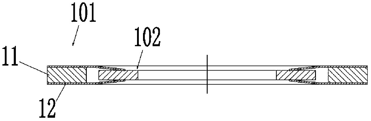
[0022] Examples of rotating conductive mechanisms, such as Figure 1-3 As shown, the rotating conductive mechanism includes an electric brush contact 101 and an electric slip ring 102.

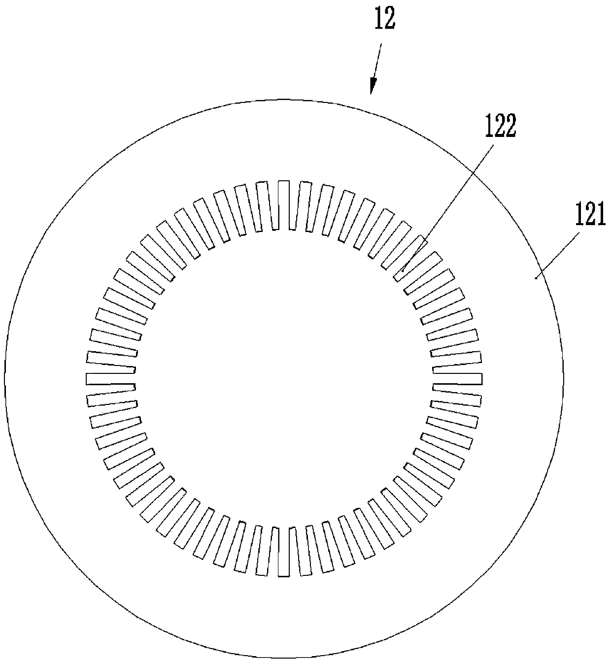
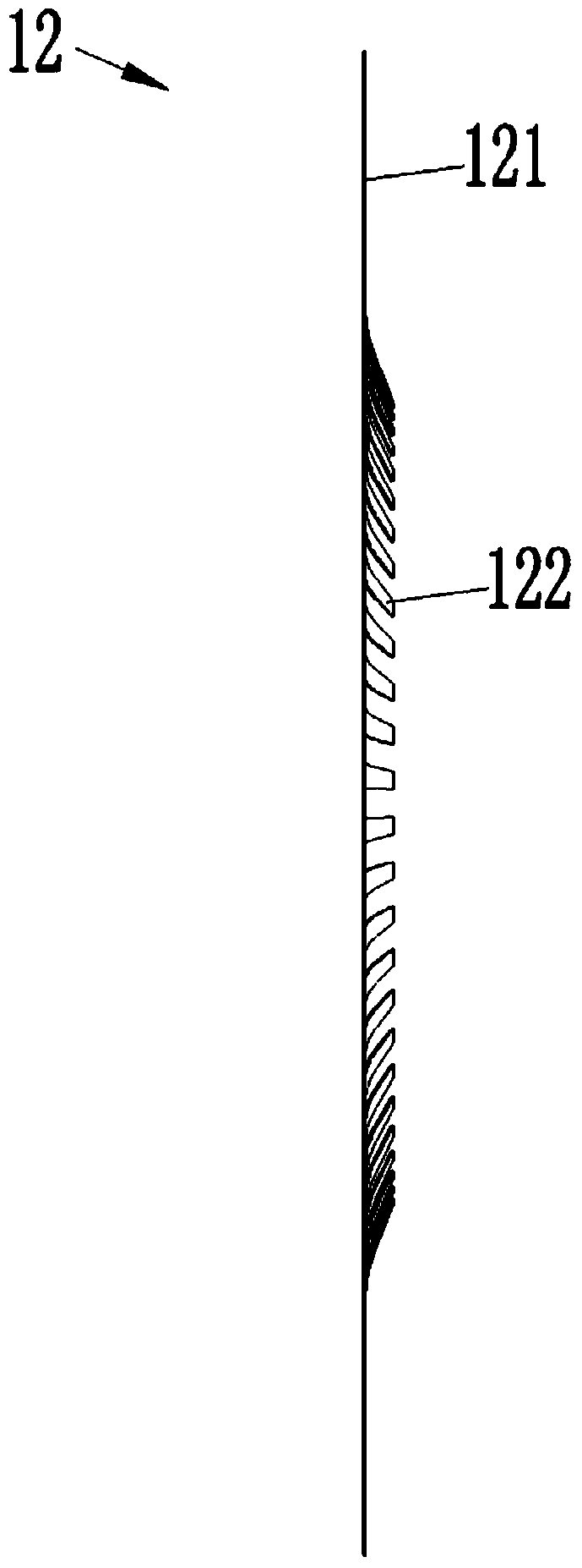
[0023] The brush contact 101 includes a conductive ring 11 and a contact spring 12, and the conductive ring 11 and the electric slip ring 102 are coaxially sleeved on the electric slip ring 102. In this embodiment, contact springs 12 are attached to the two axial sides of the conductive ring 11 respectively. Each contact spring 12 includes a mother ring 121. In this embodiment, the mother ring 121 is a circular ring and is made of copper. A circle of cantilevered elastic contact fingers 122 are provided on the inner side of the mother ring 121. The elastic contact fingers 122 surround the mother ring 121. In this embodiment, the elastic contact fingers 122 and the mother ring 121 are an integral structure, which is formed by punching. Each elastic contact finger 122 includes a fixed end on the m...


PUM


Abstract

The invention relates to the field of electrical couplers, particularly to a rotary conducting mechanism and a rotary electrical coupler with the same. The rotary conducting mechanism comprises brush contacts and electric slip rings. Each brush contact comprises a conductive ring. A contact spring is adhered to at least one side of each conductive ring and comprises a main ring. Elastic contact pins which are in cantilever shapes and arranged on the insides of the main rings comprise fixed ends and contact ends. The contact ends compress the corresponding end faces of the electric slip rings. The threadlike brush contacts of the prior art are eliminated, thus required transmission power of the contact springs is met by adjusting thickness, diameter and the like of the contact springs. With changes of the contact structure, the elastic contact pins can be matched with the electric slip rings with larger sizes, in this way, at the premise that the axial dimension of the rotary electrical coupler is maintained, the transmission power of the rotary electrical coupler is improved.

Description

Technical field [0001] The present invention relates to the field of electrical connectors, in particular to a rotary conductive mechanism and a rotary electrical connector using the mechanism. Background technique [0002] The brush contact and the electric slip ring are the two core components of the rotating electrical connector. The brush contact is often fixed on the housing of the rotating electrical connector, while the electric slip ring is fixed on a rotating shaft. Above, when the rotating shaft rotates around the axis, the brush contacts cooperate with the electric slip ring to realize the uninterrupted transmission of electric signals. Most of the current brush contacts are wire-shaped, which are eight-shaped and clamped on the corresponding electric slip ring. They mainly include composite brush block type, precious metal monofilament type and fiber brush type. For example, the application number is 201010227485 The Chinese patents of 2010202597743, 201020597669, 20...

Claims


Application Information

Patent Timeline
Patent Type & Authority Applications(China)
IPC IPC(8): H01R39/08H01R39/24
Inventor 乔永红朱晓东
Owner CHINA AVIATION OPTICAL-ELECTRICAL TECH CO LTD
Features
  • R&D
  • Intellectual Property
  • Life Sciences
  • Materials
  • Tech Scout
  • Unparalleled Data Quality
  • Higher Quality Content
  • 60% Fewer Hallucinations
Learn More