

Corrugated circular pipe filter formed by plastic sinter board pipe coiling process and manufacturing method of corrugated circular pipe filter
A manufacturing method and filter technology, which are applied in chemical instruments and methods, separation methods, dispersed particle filtration, etc., can solve the problems of inability to recoil self-cleaning or cleaning, affecting the operation effect of dust removal equipment, and being easily damaged, so as to achieve the molding process. The effect of easy control, easy control of product accuracy, and short heating time
- Summary
- Abstract
- Description
- Claims
- Application Information
AI Technical Summary
Problems solved by technology
Method used
Image


Examples
Embodiment Construction
[0044] The present invention will be described in detail below in conjunction with the accompanying drawings and embodiments.
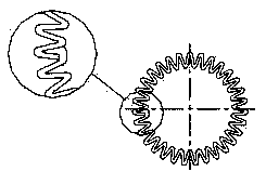
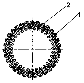
[0045] see Figure 1 to Figure 3, The present invention provides a corrugated circular tube filter formed by plastic-fired plate rolling process, the corrugated circular tube filter is mainly composed of a corrugated circular tube filter element 1 and a socket sleeve 2 .
[0046] Such as figure 1 As shown, the initial plastic-fired plate coiled pipe is a plate-shaped product, and the upper surface and the lower surface of the plate-shaped product both have a corrugated tooth-like structure.
[0047] Such as figure 2 As shown, the plate-shaped product is rolled up to form a coiled tube, and the two ends of the coiled tube are fitted and connected to each other to form a corrugated circular tube filter element 1 . Both the inner surface and the outer surface of the corrugated tube filter element 1 have a corrugated tooth structure, and the tooth str...
PUM
| Property | Measurement | Unit |
|---|---|---|
| Graininess | aaaaa | aaaaa |
Abstract
Description
Claims
Application Information