Test tube gripper, test tube labeling unit, and test tube preparing apparatus including the same

A technology of test tube clamps and test tubes, which is applied in the direction of test tube holders/clamps, packaging, identification devices, etc., which can solve the problems of difficult to change the structure of test tubes, poor installation compatibility, etc., and achieve excellent mobility, compact size, and installation compatibility Excellent effect

Active Publication Date: 2014-12-24
ENERGIUM CO LTD
View PDF5 Cites 17 Cited by
  • Summary
  • Abstract
  • Description
  • Claims
  • Application Information

AI Technical Summary

Problems solved by technology

[0029] As mentioned above, according to the labeling device disclosed in the domestic authorized patent No. 0866410, a structure that discharges the test tube that has been labeled to the bottom of the labeling device is formed. Therefore, centering on the labeling device, the upper and lower The mobile unit needs to be designed as a laminated structure, so there is a problem of poor installation compatibility
[0030] In addition, according to the labeling device disclosed in the domestic authorized patent No. 0866410, even if it is considered to attach a side discharge tool that can move the label to the side, the left side of the insertion space of the test tube that has been labeled will be driven The interference of the driving part that drives the rotation of the driving wheel, while the right side is disturbed by the driving part that pressurizes the pressure wheel, making it difficult to achieve structural changes that change the direction of test tube discharge

Method used


Image

  • Test tube gripper, test tube labeling unit, and test tube preparing apparatus including the same
  • Test tube gripper, test tube labeling unit, and test tube preparing apparatus including the same
  • Test tube gripper, test tube labeling unit, and test tube preparing apparatus including the same

Examples


Embodiment Construction

[0103] The characteristics and effects of the present invention described above or not described will be more clearly described below in conjunction with the embodiments of the present invention with reference to the accompanying drawings.

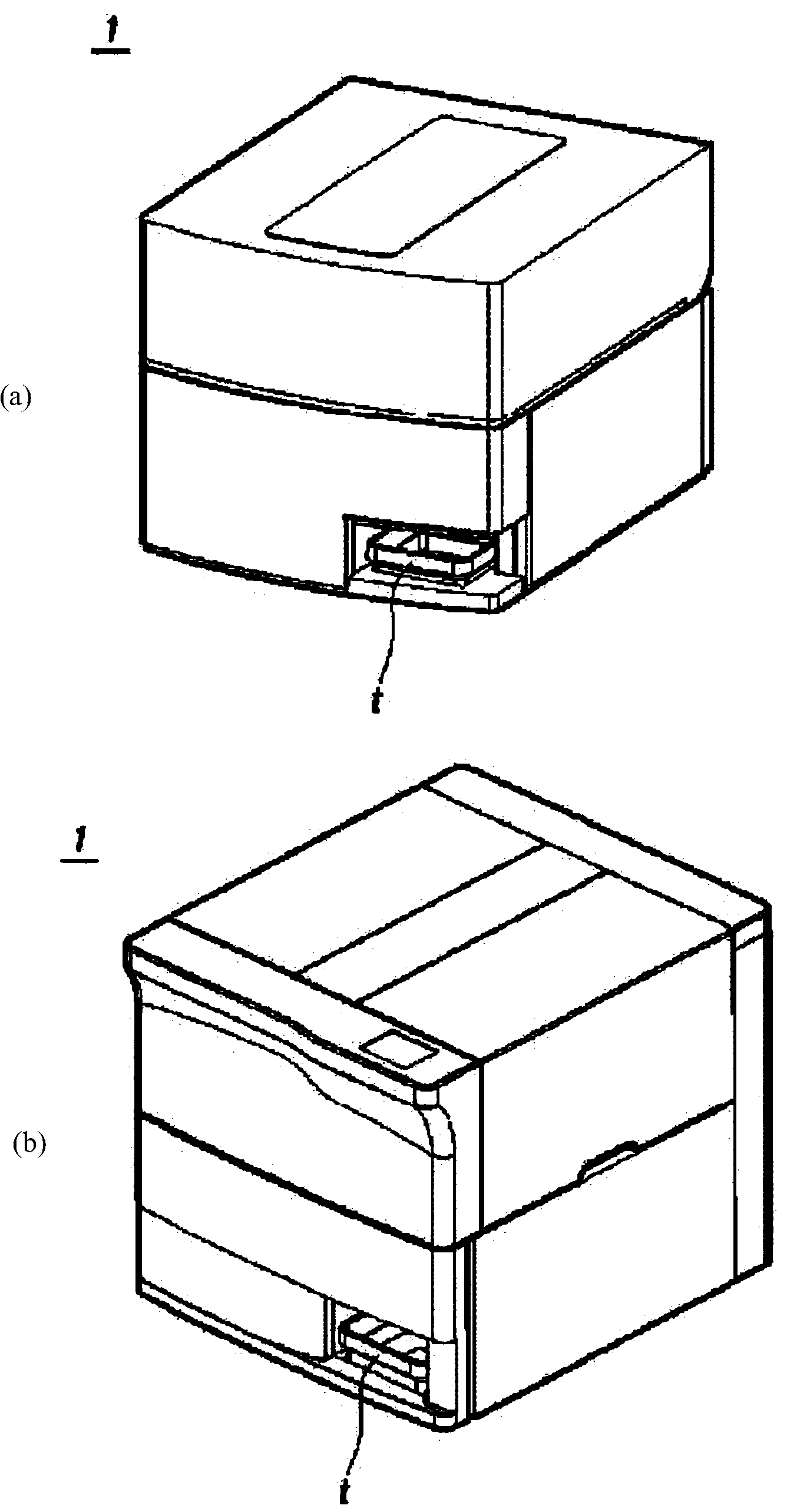
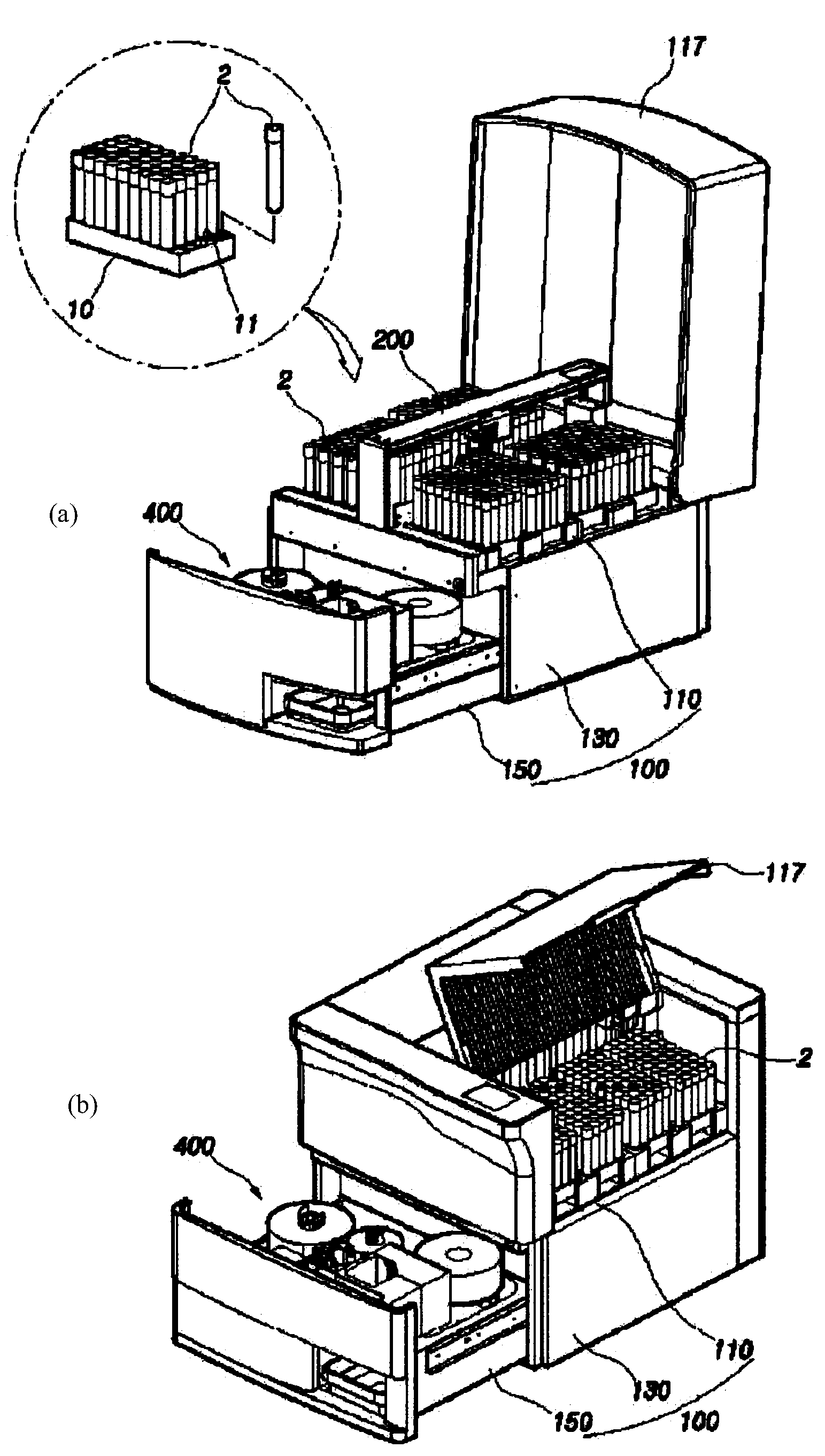
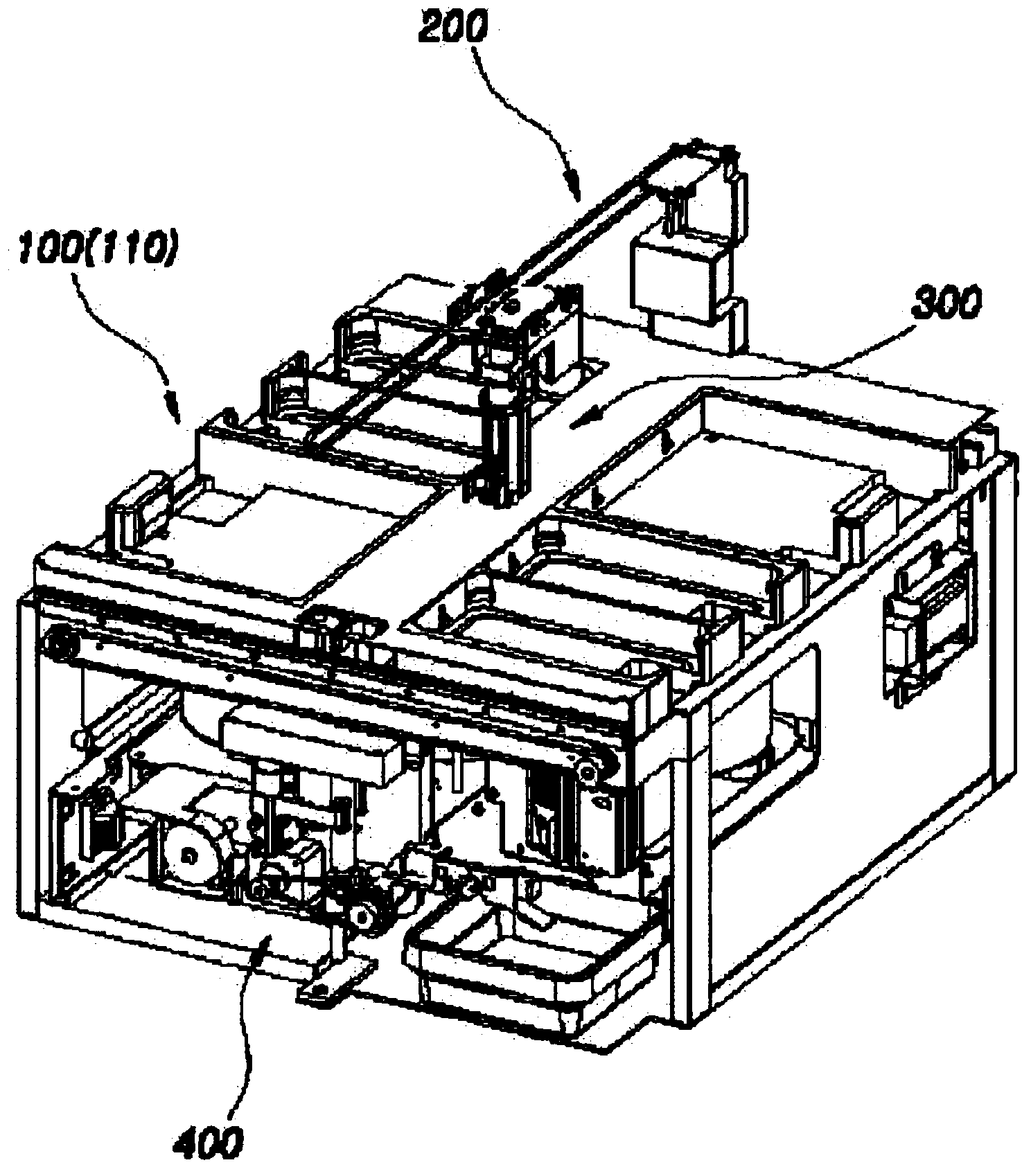
[0104] figure 1 is a perspective view of the test tube preparation device, figure 2 is a perspective view of the open test tube preparation device, image 3 is a perspective view showing the capping member of the test tube preparation device removed.

[0105] The test tube preparation device 1 according to the present invention includes a frame 100 , a clip transfer device 200 , a clip 300 , and a labeling unit 400 .

[0106] The frame 100 is used as a member supporting each unit and the test tube 2 constituting the above-mentioned test tube preparation device, and its structure includes: an upper frame 110 , a supporting frame 130 and a lower frame 150 .

[0107] refer to Figure 4 , the above-mentioned upper frame 110 has: a left ac...


PUM


Abstract

The present invention relates to a test tube preparation device, and an objective is to provide a test tube preparation device which is compact, light and more mobile and can be more rapidly and accurately handled including pinching, transferring, labelling, ejecting and the like of test tubes, by improving the spatial layout of an installing unit, a transfer unit and a label attaching unit and the constitution of the units. A technical feature of the present invention is that the constitution is made by comprising: a frame (100) in which right and left installing units (110A, 110B) where a plurality of test tubes (2) are vertically installed are provided on the upper part and at least one guide hole (115) which allows the test tube (2) to move by passing through the hole is provided between the right and left installing units (110A, 110B); a gripper transfer unit (200) which is provided to the frame (100) and transfers the test tubes (2) installed in the right and left installing units (110A, 110B) to the guide hole (115); a gripper (300) which is joined with the gripper transfer unit (200) and pinches or separates the test tubes (2); and a labelling unit (400) which is provided on the lower part of the guide hole (115) and attaches a label to the waist of the test tube (2) transferred through the guide hole (115).

Description

technical field [0001] The present invention relates to a test tube clamp, a test tube labeling unit and a test tube preparation device including the test tube, in particular to a test tube that is pasted and printed with various relevant information on test tubes used in hospitals, research institutes, universities, etc. A preparation device, a clamp for test tubes that can quickly and precisely complete the separation and movement of test tubes inserted into the tray and arranged, and a test tube labeling device, which has a swing-shaped discharge part that allows the test tubes to flow into the interior, and then switch stickers The transfer direction and transfer position of the labeled test tube, and then discharge it, so as to achieve excellent installation compatibility with the transfer unit connected to the labeling device, such as conveyors, grippers, etc. Background technique [0002] Usually, when storing various samples such as blood, animal and plant samples, a...

Claims


Application Information

Patent Timeline
Patent Type & Authority Applications(China)
IPC IPC(8): B01L3/14B01L9/06G09F3/02
CPCG01N35/0099G01N35/04B01L3/5453G01N35/00732G01N2035/00861B01L9/06B25J15/0028B65C9/30
Inventor 姜正薰李康熙朴相俊
Owner ENERGIUM CO LTD
Why Eureka
Try Eureka