Supercharge Your Innovation With Domain-Expert AI Agents!

Three-layer rotor crusher

A crusher and rotor technology, applied in grain processing, etc., can solve the problems of inconvenient installation and maintenance, large volume of counter-attack liner, uneven wear, etc., and achieve the effect of easy installation and maintenance, compact structure and light weight

Active Publication Date: 2017-06-16
ZIBO DALI MINING MASCH CO LTD
View PDF9 Cites 0 Cited by
  • Summary
  • Abstract
  • Description
  • Claims
  • Application Information

AI Technical Summary

Problems solved by technology

The installation part is easy to wear and needs to be replaced frequently, and the cost is high
Two rows or one row of cylinder counter-attack liners are installed on the barrel of the existing crusher. Each counter-attack liner is large in size and wears unevenly. If a few parts are worn out, the entire piece must be replaced, which is costly and difficult for installation and maintenance. inconvenient

Method used


Image

  • Three-layer rotor crusher
  • Three-layer rotor crusher
  • Three-layer rotor crusher

Examples


Embodiment 1

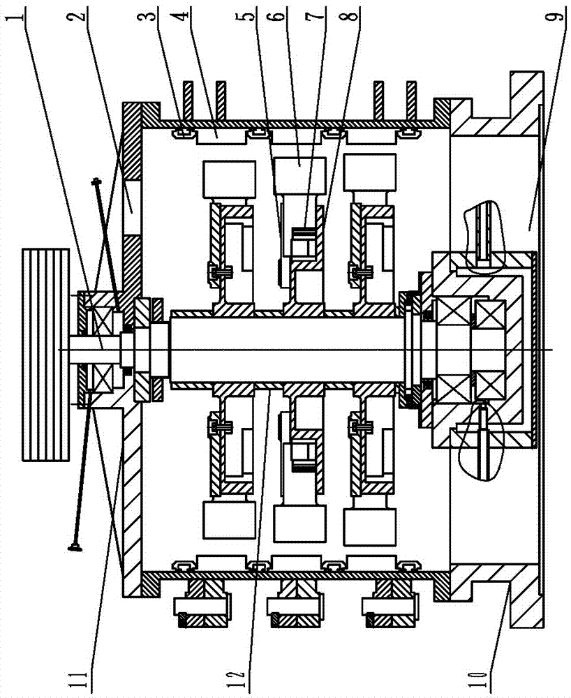
[0024] Such as figure 1 As shown, in the three-layer rotor crusher of the present invention, an upper cover 11 is installed on the upper part of the crusher cylinder, and the upper cover 11 is provided with a feed port 2 . A base 10 is installed on the lower part of the crusher barrel, and a discharge port 9 is opened on the base 10 .

[0025] The main shaft 1 is installed in the cylinder, and the three-layer rotor body 8 is installed on the main shaft 1. The shaft sleeve 12 is placed on the main shaft 1 between the rotor bodies 8. By changing the length of the shaft sleeve 12, the distance between the rotor bodies 8 is changed. The rotor body guard plate 5 is installed on the rotor body 8 . On the inner wall of the crusher cylinder, three layers of ring-shaped counter-attack linings are installed by using bolts, nuts and lining strips 3, and each counter-attack lining layer contains 12 wear-resistant counter-attack linings 4 to protect the cylinder. . The working surface o...

Embodiment 2

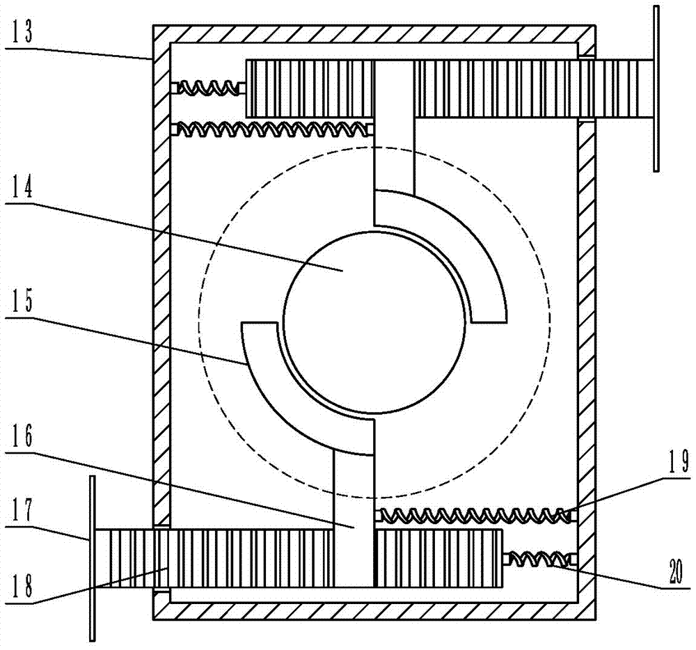
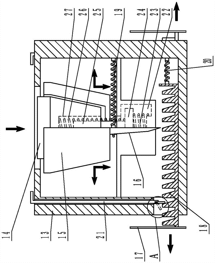
[0030] Such as Figure 2-4As shown, in this embodiment, the adjustment device is a push-type gap adjuster. The push-type gap adjuster includes a housing 13, and a frustum-shaped adjustment block 14 with a large top and a small bottom is arranged in the casing 13. The bottom surface of the adjustment block 14 is provided with a level The spring groove 27 is provided with a primary spring 26 in the spring groove, and the primary spring 26 is sleeved on the spring column 25, and the lower end of the spring column 25 is installed on the column platform 24; the secondary spring groove 22 is set below the adjustment block 14, A secondary spring 23 is arranged in the secondary spring groove 22, and the upper end of the secondary spring 23 bears against the lower surface of the column base 24; it also includes two movable blocks 15 with an "L" shape in cross section, and the movable block 15 is arranged on the adjustment block 14 The two sides of the movable block 15 and the adjacent ...


PUM


Abstract

The invention provides a three-layer-rotor crusher, and belongs to the field of crushing equipment. The three-layer-rotor crusher comprises a barrel body; a main shaft is mounted in the barrel body; a three-layer-rotor body is mounted on the main shaft; a rotor body protecting plate is mounted on the three-layer-rotor body; a countering lining board is mounted on the inner wall of the barrel body through a lining board pressing strip. The three-layer-rotor crusher further comprises a wearable impacting plate which is mounted to the three-layer-rotor body through an adjusting device; the wearable impacting plate and the countering lining board are oppositely arranged; a crushing clearance which is gradually reduced from top to bottom is reserved between the wearable impacting plate and the countering lining board. According to the three-layer-rotor crusher, the crushing clearance between the wearable impacting plate and the countering lining board can be adjusted to crush gravel of various particle diameters; in addition, the crushing clearance is gradually reduced from top to bottom, thus high crushing ratio and high crushing rate can be reached by three-layer crushing, large gravel can be once directly crushed to be the sand for construction, and as a result, the production efficiency is greatly raised.

Description

technical field [0001] The invention belongs to the field of crushing equipment, and in particular relates to a three-layer composite rotor body vertical shaft crusher. Background technique [0002] Natural sand and gravel are non-renewable resources in a short period of time. With the rapid development of my country's infrastructure construction, natural sand and gravel are almost exhausted, and the excavation of sand and gravel has caused devastating damage to resources and the environment. Due to flood control, environmental protection, resources and many other factors, many cities have banned the use of natural sand. Stone materials such as rocks and ores can be crushed into industrial sand to replace natural sand. [0003] Existing vertical shaft crushers mostly adopt a two-layer rotor structure, and the inner cavity of the crusher is not fully utilized. During the process of materials entering the inner cavity from the feed port to falling from the discharge port, the...

Claims


Application Information

Patent Timeline
Patent Type & Authority Patents(China)
IPC IPC(8): B02C13/14B02C13/20B02C13/282B02C13/28B02C13/26
Inventor 李天亮李兵张合
Owner ZIBO DALI MINING MASCH CO LTD
Features
  • R&D
  • Intellectual Property
  • Life Sciences
  • Materials
  • Tech Scout
  • Unparalleled Data Quality
  • Higher Quality Content
  • 60% Fewer Hallucinations
Learn More