Rapid wall base demounting and mounting component and method and lifting rod

A wall seat, fast technology, applied in the direction of spray device, water supply device, indoor sanitary pipe device, etc., can solve the problems of cumbersome and many installation steps, etc.

Active Publication Date: 2014-12-24
XIAMEN SOLEX HIGH TECH IND CO LTD
13 Cites 6 Cited by

AI-Extracted Technical Summary

Problems solved by technology

There are many installation steps for users, which i...

Abstract

The invention discloses a rapid wall base demounting and mounting component comprising a fixing seat (1), which can be fixed on wall, and an assembling seat (2). Locking portions are arranged between the fixing seat (10) and the assembling seat (20) and mutually act to each other. The rapid wall base demounting and mounting component is characterized by further comprising a pressing reciprocator (30) comprising a valve body (31) and an actuating device, and the actuating device is connected with the valve body (31) in an operation manner and allows the valve body (31) to move from a basic position to a work position; when the valve body (31) stays on the basic position, the locking portions does not work, and the fixing seat (10) is loosen from the assembling seat (20); when the valve body (31) stays on the work position, the locking portions mutually act to each other, and the fixing seat (10) is locked with the assembling seat (20). In this way, the demounting and mounting is achieved by only pressing the assembling seat, with convenience, rapidness and firm and reliable connecting realized.

Application Domain

Spraying apparatusDomestic plumbing

Technology Topic

Mechanical engineering

Image

  • Rapid wall base demounting and mounting component and method and lifting rod
  • Rapid wall base demounting and mounting component and method and lifting rod
  • Rapid wall base demounting and mounting component and method and lifting rod

Examples

  • Experimental program(1)

Example Embodiment

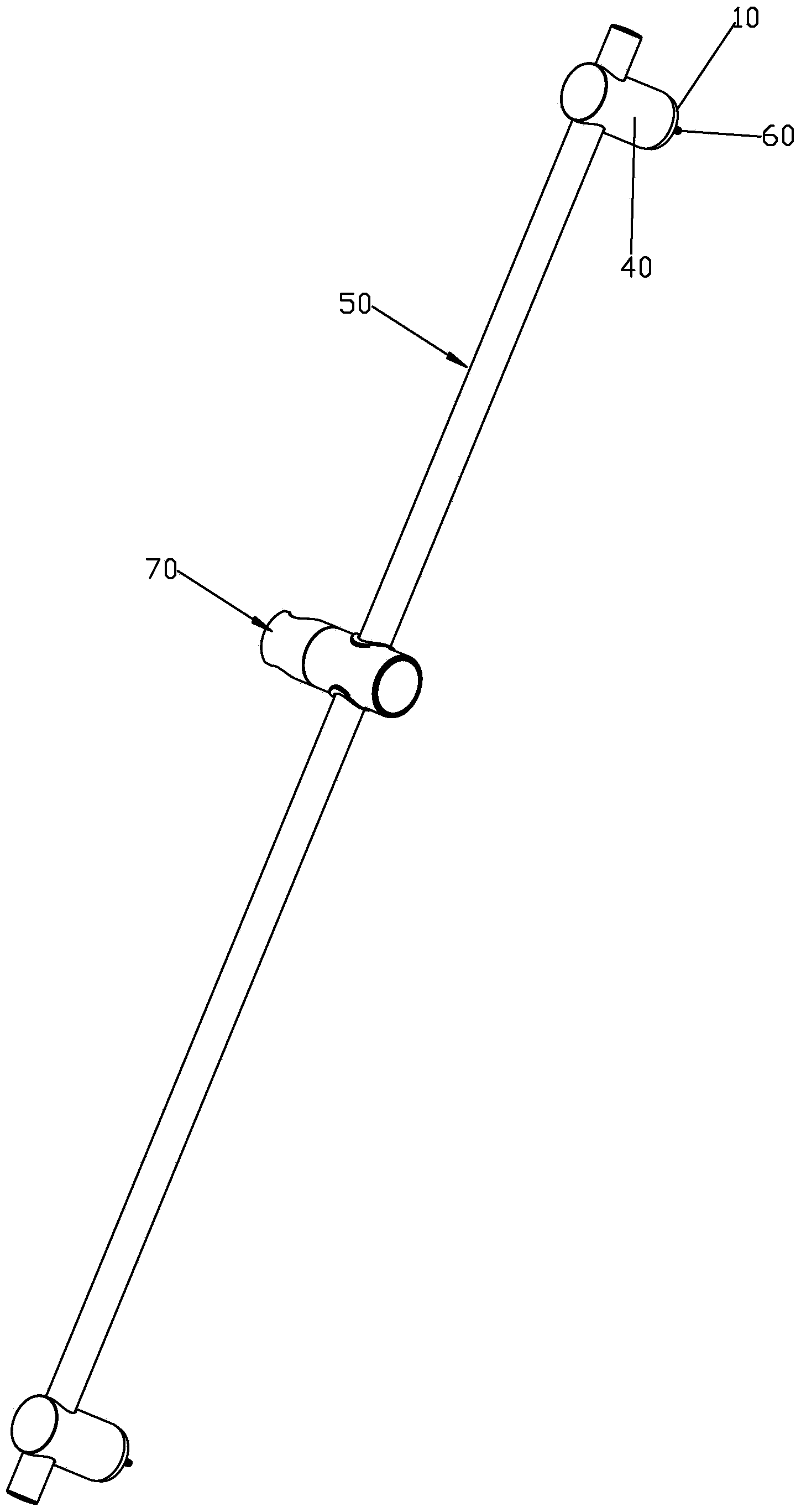
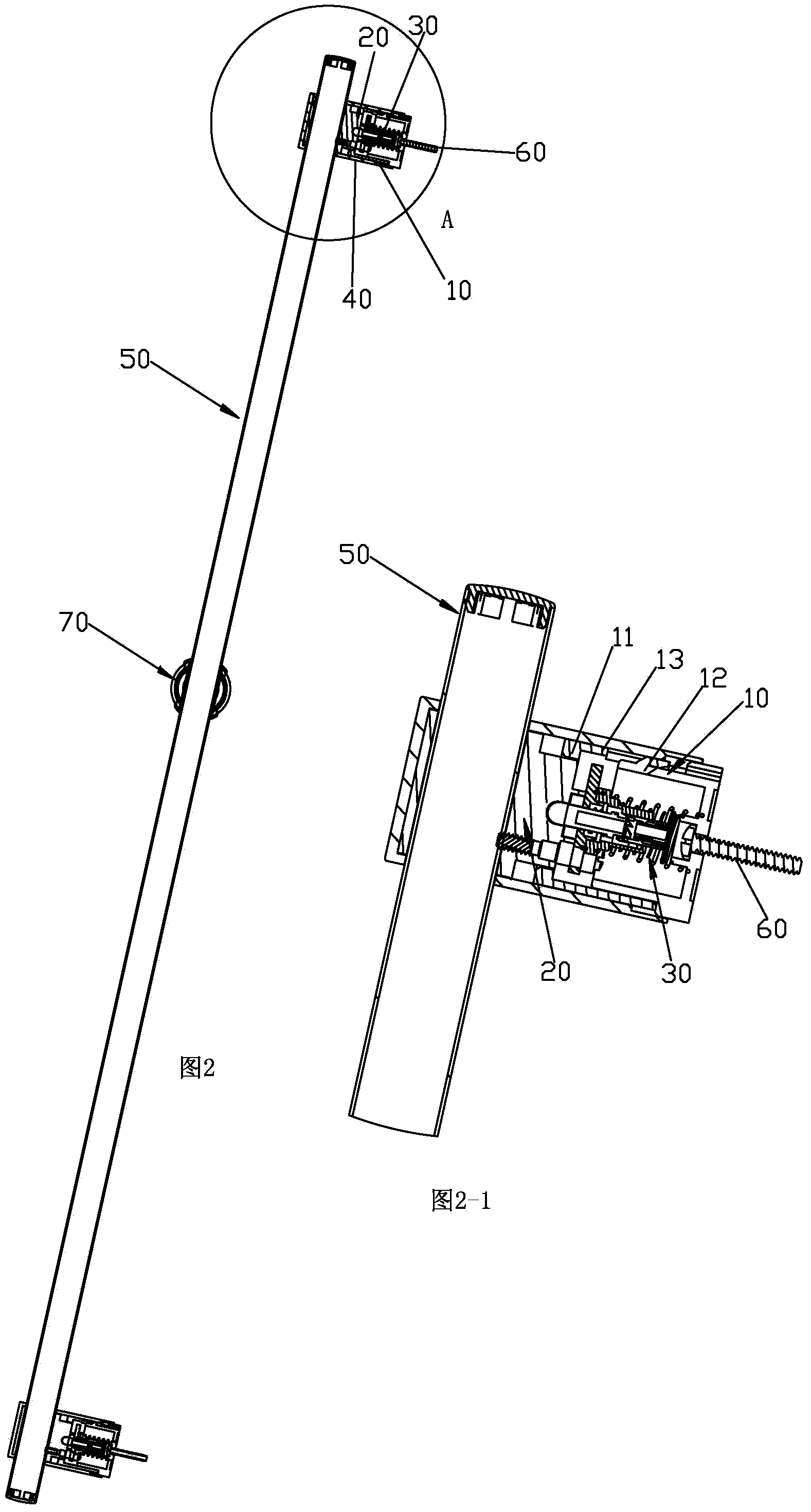
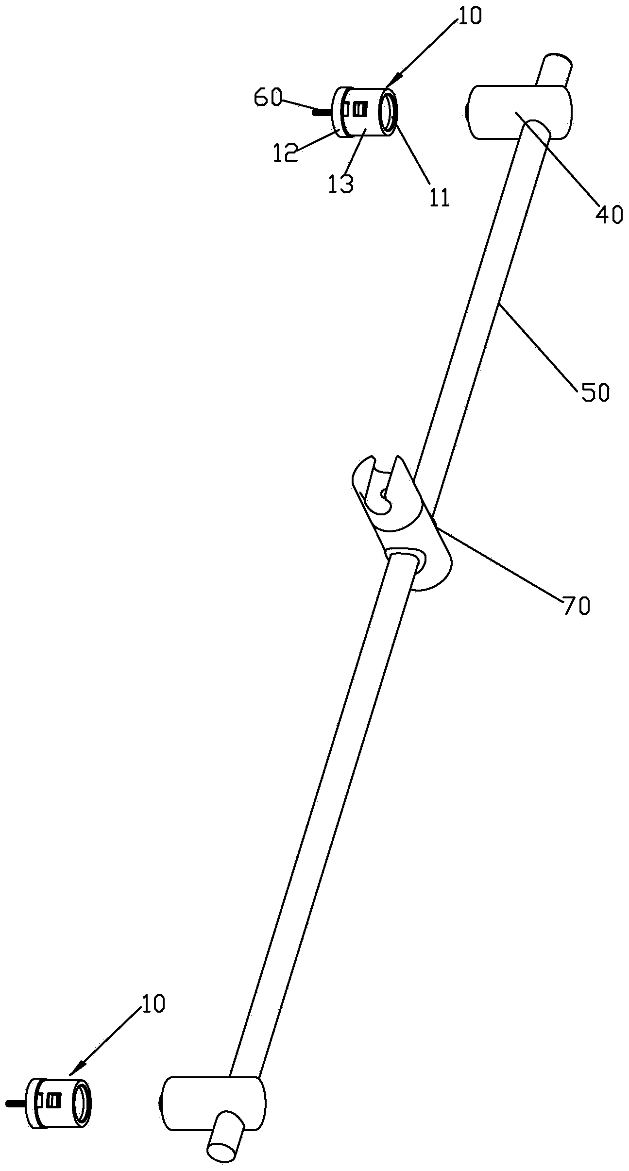
[0039] Please check Figure 1 to Figure 6 , A quick disassembly and assembly wall seat assembly, including a fixed seat 10 and an attachment seat 20.
[0040] The fixing seat 10 is recessed with an installation cavity, and the cavity of the installation cavity is provided with a hanging table 11 protruding inward, and an opening is formed in the hanging table 11. In this embodiment, the fixed seat 10 includes a base 12 and a sleeve 13. The base 12 includes a bottom wall and a peripheral wall extending from the periphery of the bottom wall perpendicular to the bottom wall. The sleeve 13 is fixedly attached to the peripheral wall. In addition, the port of the socket 13 is the cavity port, and the base 12 and the socket 13 constitute the installation cavity. According to requirements, the peripheral wall has a stepped structure, and the outer side of the small diameter of the peripheral wall of the sleeve is fixed and the end is located at the stepped surface. According to requirements, screws 60 can be used to penetrate the bottom wall to fix the fixing seat to the wall. Preferably, the hanging platform 11 has an annular plate structure.
[0041] The mounting cavity of the fixed seat 10 is equipped with an automatic ballpoint pen-type pressing and reciprocating mechanism 30. The mechanism 30 is a prior art and will not be described in further detail here. It has a valve body 31 that can slide along the vertical opening direction and be exposed. In the opening, the exposure to the opening means that in the projection along the sliding direction of the valve body 31, the valve body 31 is located in the opening, and preferably at the center. In this embodiment, the opening is parallel to the wall, and the sliding direction of the push rod is perpendicular to the wall.
[0042] The attaching seat 20 is provided with at least two sliding rods 21 that can be close to or far away from each other and sliding along the vertical direction of the valve body 31. The two sliding rods 21 and the attaching seat 20 are provided with elasticity capable of generating similar elasticity to the sliding rod 21 Body 22, the sliding rod 21 is provided with an inclined surface 23, the inclined surface 23 and the end of the valve body 31 can be matched; when the at least two sliding rods 21 are close, the at least two sliding rods 21 are adapted to the opening to be able to enter and exit the opening, the at least two sliding rods 21 When the rods 21 are far apart, the at least two sliding rods 21 can be hung on the back of the hanging platform 11, and the fixing base 10 and the attaching base 20 can be assembled and disassembled and fixed together by the sliding rod 21 and the hanging platform 11 by hooking and fitting. In this embodiment, the number of the sliding rods is two, but not limited to this, it can be at least three according to requirements, and a plurality of ring-shaped arrays are arranged and slide along the radial direction. The inclined surface is arranged on the side close to the sliding rods.
[0043] In a specific structure, the end surface of the mounting base 20 is provided with a through-hole chute 25, the end of the mounting base 20 is also mounted with a hanging plate 26, and the end of the mounting base 20 and the hanging plate 26 are aligned, fitted and fixed to make The slide groove 25 constitutes a through slide, the end of the hanging plate 26 and the attachment base 20 are all fitted to the opening, the number of the slide rod 21 is two, and the two slide rods 21 are fitted and connected in the slide way; A through hole 261 is provided in the center of 26, and the valve body 31 can pass through the through hole 261 freely. The sliding groove 25 is formed by arranging two parallel convex strips on the end surface, and the sliding groove is formed in the two convex strips. Preferably, a mounting groove 27 is recessed at the bottom of the sliding groove 25, and the proximal ends of the two sliding rods 21 are convexly provided with a protrusion 211, and the protrusion 211 is adapted to connect to the mounting groove 27, and the elastic member 22 It is a spring, which is installed in the installation groove 27 and abuts between the groove end surface of the installation groove 27 and the protruding part 211.
[0044] In this embodiment, the locking part includes a hanging table, a sliding rod and an elastic body.
[0045] According to requirements, a decorative cover 40 is further included, and the decorative cover 40 is suitable to fit outside the fixed seat 10 and the mounting seat 20.
[0046] The method for assembling and disassembling the wall seat assembly quickly; the assembling method includes:
[0047] Step 11, the mounting seat 20 is pushed into the opening of the fixed seat 10, the inclined surface 23 of the sliding rod 21 acts on the valve body 31, so that the mechanism 30 is touched, and the valve body 31 springs out;
[0048] Step 12: The end of the valve body 31 is pressed against the inclined surface, and the two sliding rods 21 are moved away from each other until the end of the valve body 31 is between the two sliding rods 21, and the two sliding rods 21 are hung on the back of the hanging platform 11 to install the The socket 20 and the fixed socket 10 are locked together;
[0049] The disconnection method includes:
[0050] Step 21, the attachment seat 20 is pushed into the opening of the fixed seat 10, the attachment seat 20 acts on the valve body 31, the mechanism 30 is touched, and the valve body 31 is reset;
[0051] Step 22, under the elastic force of the elastic body 22, the two sliding rods 21 slide close together, the sliding rod 21 is separated from the hanging platform 11, and the attachment seat 20 can be separated from the fixed seat 10.
[0052] If the above-mentioned connecting device is applied to a lifting rod, it also includes a rod 50. The number of the quick-dismounting wall base assembly is two. The mounting base 20 is provided with a through mounting hole 24 through the vertical mounting base 20. The rod 50 is adapted to be inserted into the mounting holes 24 of the two attachment bases 20, and at least one attachment base 20 and the rod 50 are configured to be detachable and fixed, for example, using screws. If a decorative cover 40 is provided, the decorative cover also needs to be provided with a through hole 41, and the through hole 41 is adapted to the mounting hole 24. A sliding seat 70 is slidably connected to the lifting rod for plugging in the shower.
[0053] In this embodiment, the connecting device is used in the lifting rod, but it is not limited to this. It can also be used as a pendant according to needs. For example, a hanging structure is provided on the mounting seat, and multiple available Choose the attachment base, each attachment base has a different attachment structure, you can select the required attachment structure to install and connect to the fixed base according to your needs.
[0054] The above are only preferred embodiments of the present invention, so the scope of implementation of the present invention cannot be limited accordingly. That is, equivalent changes and modifications made according to the scope of the present invention and the contents of the specification should still be covered by the present invention. Within range.

PUM

no PUM

Description & Claims & Application Information

We can also present the details of the Description, Claims and Application information to help users get a comprehensive understanding of the technical details of the patent, such as background art, summary of invention, brief description of drawings, description of embodiments, and other original content. On the other hand, users can also determine the specific scope of protection of the technology through the list of claims; as well as understand the changes in the life cycle of the technology with the presentation of the patent timeline. Login to view more.
Why Eureka
Try Eureka