Punching sheet painting roller transmission device

A technology of transmission device and paint roller, which is applied to the device of coating liquid on the surface, coating and other directions, which can solve the problems of non-compliance with the thickness of the punched paint film, cumbersome roller maintenance and replacement, reliability, and painting accuracy Poor and other problems, to achieve the effect of ensuring uniformity and consistency, uniform speed and consistency

Active Publication Date: 2014-12-24
HARBIN ELECTRIC MASCH CO LTD
View PDF6 Cites 3 Cited by
  • Summary
  • Abstract
  • Description
  • Claims
  • Application Information

AI Technical Summary

Problems solved by technology

[0002] Punching sheet is the core component of the generator. The thickness of the punching sheet and the required paint film thickness are different for generators of different specifications. Whether the thickness of the punching sheet paint film is uniform will directly affect the overall height of the iron core after the unit is installed with laminations. At the same time It will also have adverse effects on other performance of the generator
At present, most domestic generators are painted with equipment from the 1980s. The paint roller transmission system is mostly driven by chains or gears. Because the speed of each paint roller is stepped, the speed of the main and auxiliary paint rollers does not match. , often cause the paint film thickness of the punched sheet to not meet the requirements. At the same time, after long-term use, the paint roller speed is uneven due to the wear of the mechanical transmission system, which will cause the problem of inconsistent paint film thickness between the punched sheets of the same unit; the paint roller support is mostly Fixed type, it is not convenient to adjust according to the thickness requirements of punching sheet and paint film. In short, the structure of the paint roller transmission system of the existing equipment is complicated, the maintenance and replacement of the roller are cumbersome, the reliability and painting accuracy are poor, the degree of automation is low, and the versatility is poor

Method used


Image

  • Punching sheet painting roller transmission device
  • Punching sheet painting roller transmission device
  • Punching sheet painting roller transmission device

Examples


Embodiment Construction

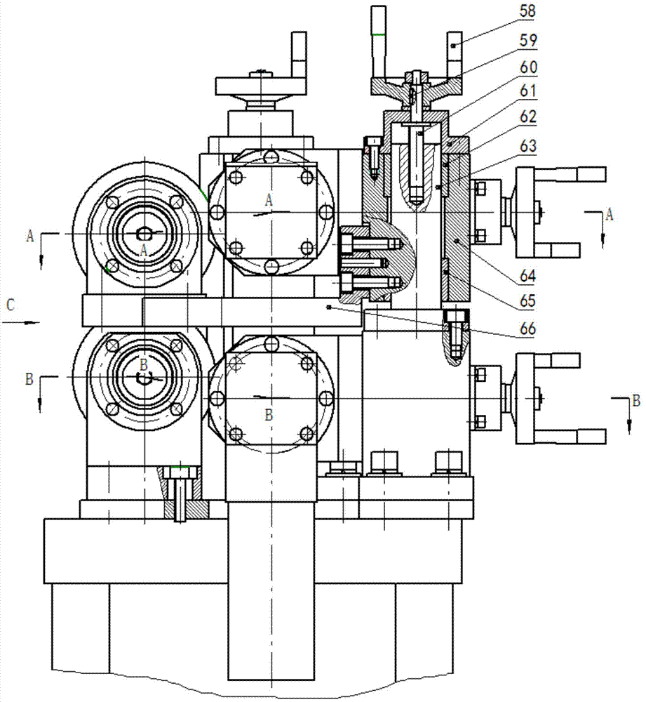
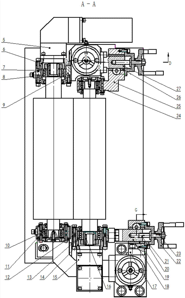
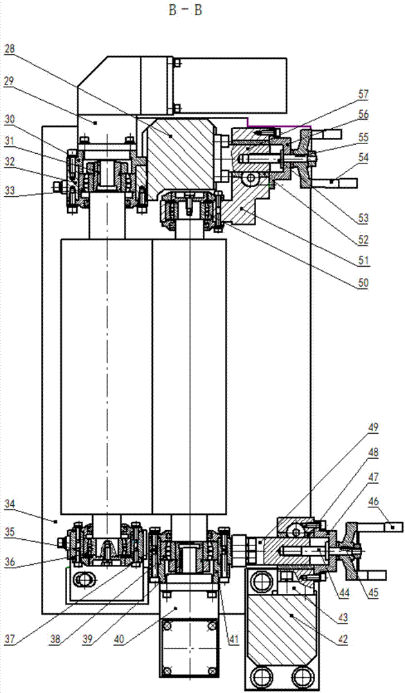
[0017] Such as figure 2 , image 3 , Figure 4 , Figure 5 As shown in the figure, a transmission device for film coating rollers, the non-driving ends of the main paint roller I1, the main paint roller II2 and the driving ends of the distribution paint roller I4 and the distribution paint roller II3 are located on one side of the device, the main paint roller I1, the main paint roller The driving end of paint roller Ⅱ2 and the non-driving ends of paint roller Ⅰ4 and paint roller Ⅱ3 are located on the other side of the device; the axes of main paint roller Ⅰ1, paint roller Ⅱ2, paint roller Ⅰ4 and paint roller Ⅱ3 are parallel to each other. Paint roller Ⅰ1 and matching paint roller Ⅰ4 are located above the main paint roller Ⅱ2 and matching paint roller Ⅱ3; , The outer ring of the bearing Ⅱ36 is connected with the inner hole of the bearing seat Ⅰ11 and the bearing seat Ⅱ35, such as figure 1As shown, the bearing seat I11 is connected with the sliding seat I64 through the bra...


PUM


Abstract

The invention discloses a punching sheet painting roller transmission device. Each main paint roller is driven by a servo reducer and each auxiliary paint roller which is matched with the corresponding main paint roller is driven by a servo reducer; a moveable main paint roller driving end and a corresponding auxiliary paint roller non-driving end are supported on a sliding base; a moveable main paint roller non-driving end and a corresponding auxiliary paint roller driving end are supported on a sliding base; a fixed main paint roller driving end and a corresponding auxiliary paint roller non-driving end are supported on a fixed base; a fixed main paint roller non-driving end is supported on a frame and an auxiliary paint roller non-driving end which is matched with the fixed main paint roller non-driving end is supported on a fixed base; a space between the two main paint rollers can be accurately adjusted through the manual rotation of handles which are arranged on the sliding bases arranged at the two ends of the moveable main paint roller respectively; a space between each auxiliary paint roller and the corresponding main paint roller can be accurately adjusted through the manual rotation of handles which are arranged at the two ends of each auxiliary paint roller respectively. The punching sheet painting roller transmission device has the advantages of being high in paint roller rotating speed accuracy, wide in speed adjustment range, high in adaptability, stable and reliable in work and high in automation degree.

Description

Technical field: [0001] The invention relates to a driving device for a punching paint roller. Background technique: [0002] Punching sheet is the core component of the generator. The thickness of the punching sheet and the required paint film thickness are different for generators of different specifications. Whether the thickness of the punching sheet paint film is uniform will directly affect the overall height of the iron core after the unit is installed with laminations. At the same time It will also have adverse effects on other performances of the generator. At present, most domestic generators are painted with equipment from the 1980s. The paint roller transmission system is mostly driven by chains or gears. Because the speed of each paint roller is stepped, the speed of the main and auxiliary paint rollers does not match. , often cause the paint film thickness of the punched sheet to not meet the requirements. At the same time, after long-term use, the paint rolle...

Claims


Application Information

Patent Timeline
IPC IPC(8): B05C11/02B05C1/08
Inventor 葛军杨宏伟肖军李工李冰刘雅兰刘敏张宁李晨晨
Owner HARBIN ELECTRIC MASCH CO LTD
Why Eureka
Try Eureka