Rolling shaft type tongs

A technology of pliers and rollers, applied in the field of pliers, which can solve the problems of excessive bite of the pliers mouth, damage to objects, and the inability of users to cut objects easily, so as to achieve the effect of convenient use and prevention of damage to objects

Active Publication Date: 2014-12-24
SUZHOU HAOYUN ELECTRONICS TECH CO LTD
View PDF6 Cites 0 Cited by
  • Summary
  • Abstract
  • Description
  • Claims
  • Application Information

AI Technical Summary

Problems solved by technology

[0002] Common pliers are composed of pliers mouth, pliers plug and handle. According to the principle of leverage, hold the handle when cutting an object, close the pliers mouth, and use a small force to cut the object. The user may not be able to cut the object easily; in addition, the distance between the handles is very small, if excessive force is accidentally applied, it will cause excessive bite at the jaws and damage the object

Method used


Image

  • Rolling shaft type tongs
  • Rolling shaft type tongs

Examples


Embodiment

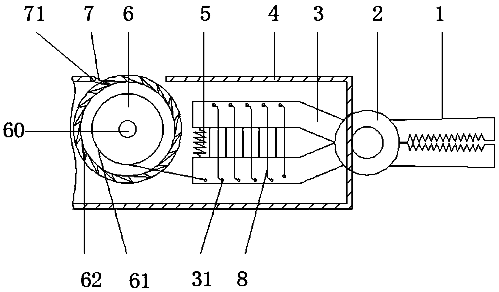
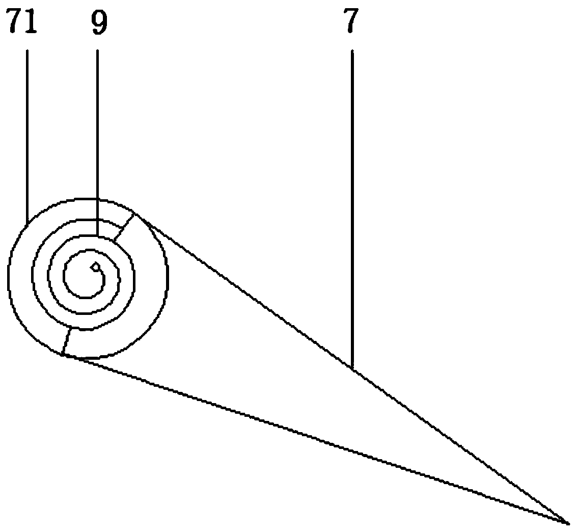
[0013] exist figure 1 , figure 2 In the embodiment shown, the roller type pliers include a pliers mouth 1, a pliers cheek 2, a handle 3, and a casing 4 surrounding the handle; the ends of the two arms of the handle 3 are connected to a compression spring 5; The two ends are respectively connected to the two arms of the handle 3; the two arms of the handle 3 each have a row of through holes 31 evenly arranged in the axial direction, and there is a metal wire 8 between the two arms of the handle 3, and the metal The wire 8 forms a spiral shape and passes through each of the through holes 31 in turn. The edge of the through hole 31 is rounded, and the metal coil is wound on the handle 3 for 5 times. The rounded shape can effectively reduce the metal The frictional force of the wire 8 sliding at the through hole 31; one end of the metal wire 8 is fixed on the handle 3, and the other end is connected to a wire winding reel 6 with a wire winding slot 61; the wire reel 6 passes thr...


PUM


Abstract

The invention relates to a pair of rolling shaft type tongs. The pair of rolling shaft type tongs comprises a tong hook, a tong gill, a handle and a shell enclosing the handle, wherein the tail ends of two arms are connected with a compression spring; two arms of the handle are respectively provided with a row of through holes uniformly distributed along the axial direction; a metal wire is arranged between the two arms of the handle, is spiral and sequentially passes through the through holes; one end of the metal wire is fixedly arranged on the handle, and the other end of the metal wire is connected to a wire spool with a wire winding groove; the wire spool is connected to the shell by virtue of a wire winding shaft and can rotate around the wire winding shaft freely; the periphery of the wire spool is provided with ratchets; the ratchets are matched with pawls on the shell; the pawls are rotatably connected to the shell by virtue of pawl shafts; the shell is provided with a window capable of exposing the wire spool. The pair of rolling shaft type tongs can be used for easily clipping objects with high rigidity and effectively preventing object damage caused by overlarge forces.

Description

technical field [0001] The present invention relates to a hardware appliance, in particular, a pair of pliers. Background technique [0002] Common pliers are composed of a pliers mouth, a pliers plug and a handle. According to the principle of leverage, hold the handle when the object needs to be cut, close the pliers mouth, and use a small force to cut the object, but when cutting objects with greater hardness The user may not be able to easily cut the object; in addition, the distance between the handles is very small. If the force is too strong, it will cause excessive bite at the jaws and damage the object. SUMMARY OF THE INVENTION [0003] In view of the above problems, the purpose of the present invention is to provide a roller type pliers, which can easily cut objects with high hardness and can effectively prevent damage to the objects caused by excessive force. [0004] In order to solve the above problems, the technical scheme of the present invention is as foll...

Claims


Application Information

Patent Timeline
Patent Type & Authority Applications(China)
IPC IPC(8): B25B7/00B25B7/12
CPCB25B7/00B25B7/12
Inventor 马志明
Owner SUZHOU HAOYUN ELECTRONICS TECH CO LTD
Why Eureka
Try Eureka