Forced feeding device

A technology of feeder and feed port, which is applied in the field of feeding equipment, can solve the problems of unsmooth feeding and easy powder leakage, and achieve the effect of ensuring uniformity and maintaining stability

Active Publication Date: 2014-12-24
北京国药龙立科技有限公司
View PDF10 Cites 7 Cited by
  • Summary
  • Abstract
  • Description
  • Claims
  • Application Information

AI Technical Summary

Problems solved by technology

[0009] The present invention solves the problems of unsmooth feeding and easy powder leakage existing in the forced

Method used


Image

  • Forced feeding device
  • Forced feeding device
  • Forced feeding device

Examples


Embodiment 1

[0047] The forced feeder described in this embodiment includes an impeller box 1, and a feed inlet 2 is arranged on the upper surface of the impeller box 1; an upper impeller chamber 3 and a lower impeller chamber are also arranged in the impeller box 1. 5 and a partition between the upper impeller cavity 3 and the lower impeller cavity 5, wherein:

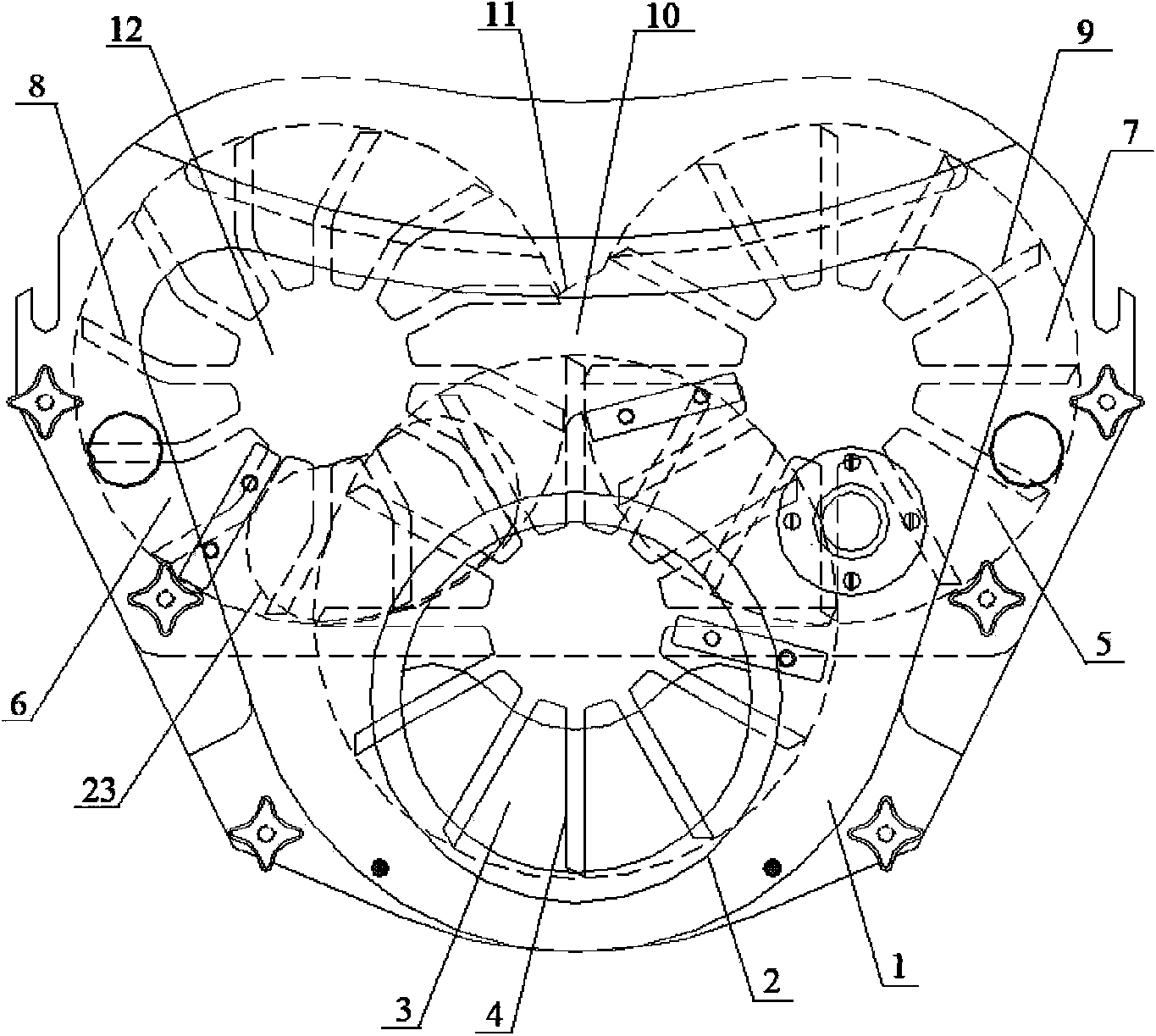
[0048] Such as figure 2 As shown, the upper impeller chamber 3 is communicated with the feed inlet 2, and a distribution impeller 4 is arranged in the upper impeller chamber 3, and the distribution impeller 4 is arranged below the feed inlet 2. ;

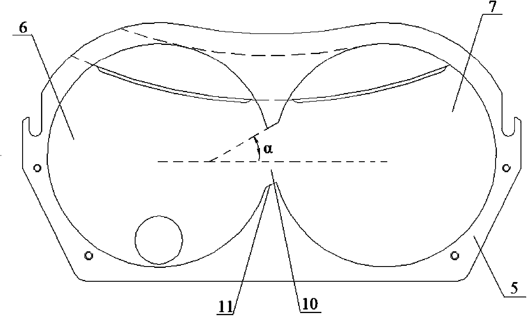
[0049] The lower impeller chamber 5 is located below the upper impeller chamber 3 and includes a feeding impeller chamber 6 and a quantitative impeller chamber 7. The junction of the feeding impeller chamber 6 and the quantitative impeller chamber 7 is communicated. A feeding impeller 8 is arranged in the impeller chamber 6, a quantitative impeller 9 is arranged in the quantitative i...

Embodiment 2

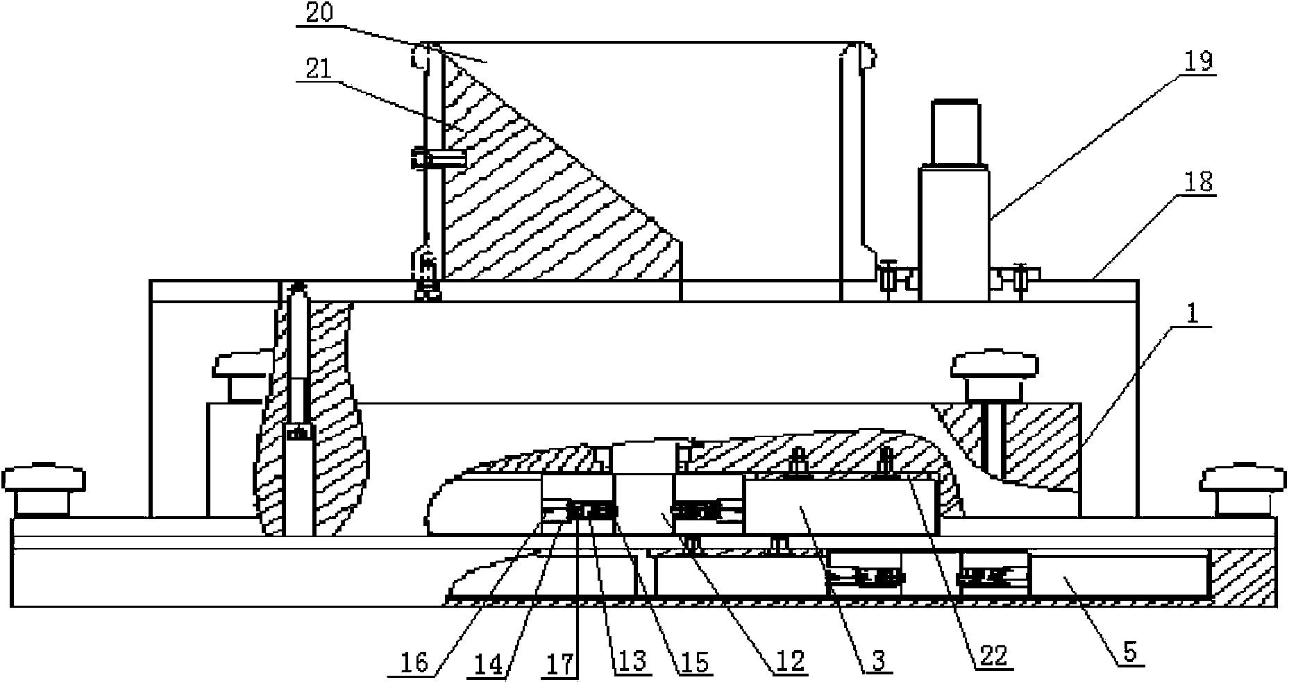
[0057] See figure 1 , the forced feeder described in this embodiment includes an impeller box 1, a gear box 18 and a feeding cylinder 20, please also refer to figure 2 , the upper surface of the impeller box 1 is provided with a feed inlet 2; in the impeller box 1, there are also: an upper impeller chamber 3, a lower impeller chamber 5, and an upper impeller chamber 3 and a lower impeller chamber. Partition between chambers 5, wherein:

[0058] The upper impeller chamber 3 is communicated with the feed inlet 2, and a distribution impeller 4 is arranged in the upper impeller chamber 3, and the distribution impeller 4 is arranged below the feed inlet 2;

[0059] The lower impeller cavity 5 is located below the upper impeller cavity 3, and includes a feeding impeller cavity 6 and a quantitative impeller cavity 7 communicated at the junction, both of which have a diameter of 168mm. Feed impeller 8, the gap between the feed impeller 8 and the wall of the feed impeller chamber 6 ...


PUM

PropertyMeasurementUnit
Diameteraaaaaaaaaa

Abstract

The invention discloses a forced feeding device. The forced feeding device comprises an impeller box, wherein an upper-layer impeller chamber, a lower-layer impeller chamber and a separation plate arranged between the upper-layer impeller chamber and the lower-layer impeller chamber are arranged in the impeller box; the upper-layer impeller chamber is internally provided with a material distribution impeller and the lower-layer impeller chamber comprises a feeding impeller chamber and a quantitative impeller chamber; a crossed part of the feeding impeller chamber and the quantitative impeller chamber is communicated; a feeding impeller is arranged in the feeding impeller chamber; a quantitative impeller is arranged in the quantitative impeller chamber; the rotating direction of the feeding impeller is opposite to the rotating direction of the material distribution impeller. According to the forced feeding device, the quantitative impeller chamber is arranged and surplus materials in the quantitative impeller chamber are added into the feeding impeller chamber again so that the materials flow smoothly in the forced feeding device; a material caking phenomenon is avoided so that the filling stability of the materials is ensured.

Description

technical field [0001] The invention relates to a forced feeder, in particular to a forced feeder for a high-speed tablet press, and belongs to the technical field of feeding equipment. technical background [0002] The forced feeder is a feeding device widely used in high-speed rotary tablet presses in recent years. Its working principle is: the material flowing down from the tablet press barrel is evenly filled into the into the die hole of the punching plate of the tablet press. Due to the forced filling of the material, the speed of the punching plate of the tablet press is greatly increased, which greatly shortens the filling time of the material. [0003] As we all know, the rotary speed of the high-speed tablet press is very fast. In this high-speed operation, in order to ensure the stability of the tablet weight, it is required that the material delivery must be uniform and smooth. The structure and size of the impeller in the forced feeder directly affect the unif...

Claims


Application Information

Patent Timeline
IPC IPC(8): B30B15/30
CPCB30B11/08B30B15/308
Inventor 程宝善
Owner 北京国药龙立科技有限公司
Why Eureka
Try Eureka