Bottle arranging machine

A technology of a bottle unscrambler and a fan, applied in the field of bottle unscramblers, can solve the problems of reducing production efficiency, affecting the probability of plastic bottles entering the working position, and poor connection between bottles and filling lines, and achieving the effect of improving bottle unscrambling efficiency.

Inactive Publication Date: 2014-12-24
李士羽
View PDF7 Cites 5 Cited by
  • Summary
  • Abstract
  • Description
  • Claims
  • Application Information

AI Technical Summary

Problems solved by technology

Although this bottle unscrambler has a simple structure, it has the following disadvantages: 1. This inclined structure can only place bottles at the low position of the turntable, so that the high position of the working position is not effectively utilized.
2. All plastic bottles gather at the low position of the turntable, which affects the probability of plastic bottles entering the working position and affects the bottle unscrambling efficiency of the bottle unscrambler
3. This bottle unscrambler is only suitable for thick and heavy bottles, not suitable for thin and light bottles
[0004] Another example is the bottle unscrambler of a factory in Songyuan. Plastic bottles need to fall into the fixed cabinet on the edge of the rotating body. This structure limits the height and diameter of the bottle, which limits the manufacturer's requirements for different weights and bottle shapes. When the bottle falls into the cabinet, it will scratch the bottle and affect the appearance of the bottle. The anti-bottle turning mechanism will squeeze and jam the bottle during the turning process for thin-walled and light-weight bottles. Affecting the working efficiency of the machine, the bottle unscrambler outputs the bottle forward by pushing the bottle by the bottle body to connect with the filling line, so that the bottle with thin wall is easy to be squeezed and deformed, making the bottle and the filling machine The poor connection of the filling line affects the stability of the filling production and reduces the production efficiency

Method used


Image

  • Bottle arranging machine
  • Bottle arranging machine
  • Bottle arranging machine

Examples


Embodiment Construction

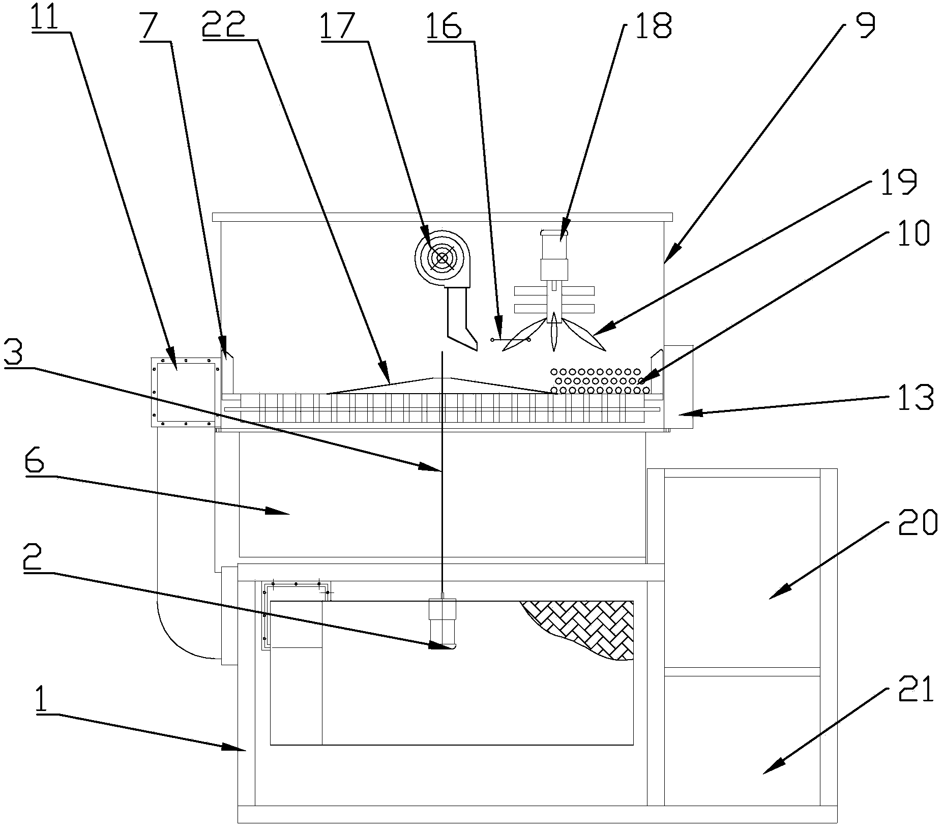
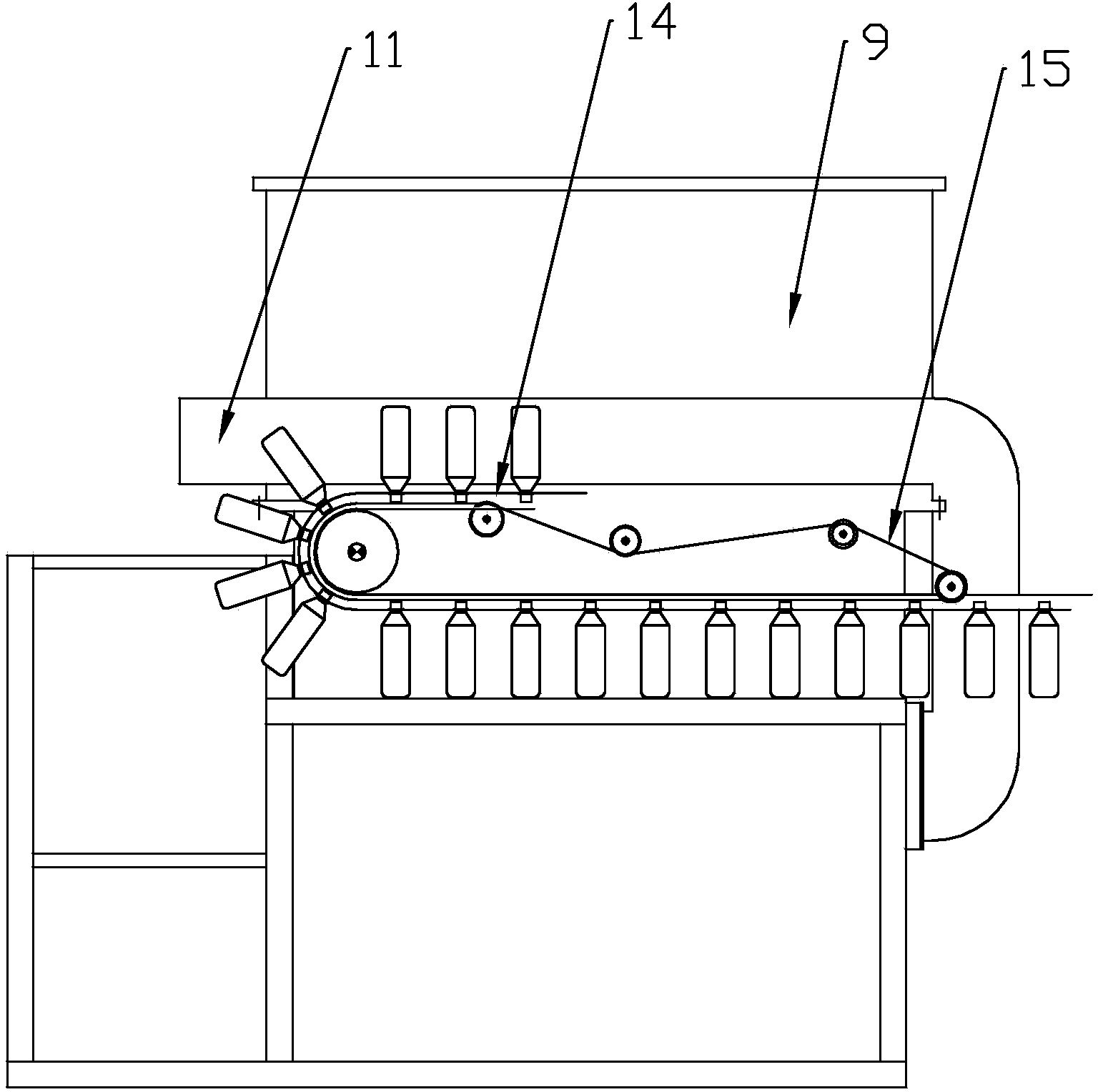
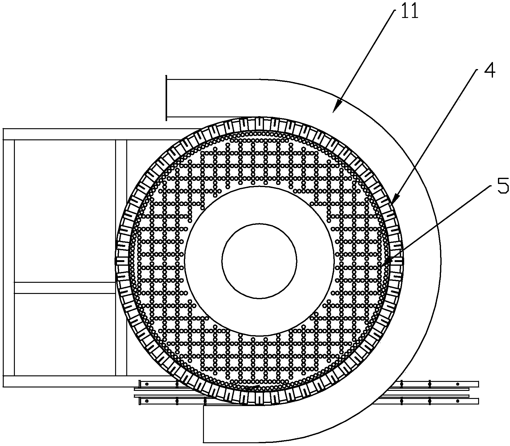
[0032] As shown in 1-3, a bottle unscrambler includes a frame 1, a fan on the frame 1, a motor 2, and the fan communicates with the upper air chamber 6 through the pipeline I, and the upper part of the air chamber 6 is provided with a The motor 2 is connected to the turntable 4 through the main shaft 3. The middle part of the turntable 4 is provided with a conical protrusion 22 coaxial with the turntable 4. The turntable 4 is provided with several vertically upward guiding air ducts 5, and several guiding air ducts 5 are arranged alternately. composed as image 3 The several frame shapes shown can also form several circles, triangles, rhombuses, polygons or irregular figures depending on the type of bottle 50 as the case may be. The blower fan communicates with the guide air duct 5 through the air chamber 6, and the edge of the turntable 4 is provided with several such as Figure 6 The limiting mechanism shown, the limiting mechanism includes a bottle body baffle 7, a bottle ...


PUM


Abstract

The invention creatively discloses a bottle arranging machine. The bottle arranging machine is provided with a machine frame, wherein an air blower and a motor are arranged on the machine frame, an air chamber is arranged above the air blower, a turntable which is connected with the motor through a main shaft is arranged above the air chamber, a plurality of vertical upward guiding air passages are formed in the turntable, the air blower is communicated with the air chamber through a pipeline I, a plurality of limiting mechanisms are arranged at the edge of the turntable, and each limiting mechanism comprises a bottle body baffle and a bottle neck supporting block located below the corresponding bottle body baffle; the periphery of the turntable is enclosed by a shell, a plurality of through holes are formed in the shell and are communicated with a negative-pressure chamber, which is located on the external wall of the shell, so as to form a negative-pressure hole band, the shell is provided with a bottle outlet, and the bottle outlet is butted with a bottle overturning mechanism. The bottle arranging machine is simple in structure, small in size, light in weight and convenient to disassemble and assemble and meanwhile has the advantages of high bottle arranging efficiency, stability in work, strong adaptability and automation.

Description

technical field [0001] The invention relates to a bottle unscrambler, which is suitable for sorting the bottles before the filling production line. Background technique [0002] The bottle unscrambler is the pre-equipment of the filling production line. It is mainly used to put the plastic bottles into the correct working position and unscramble them in an orderly manner, and then connect the unscrambled bottles with the filling production line for production. The current existing bottle unscrambler has the defects of large volume, heavy weight, unsuitable transportation and installation, low bottle unscrambling efficiency, poor applicability, and high processing cost. [0003] For example, the bottle unscrambler of a factory in Shanghai first puts the plastic bottle into the mechanism of the working position, and is equipped with an inclined turntable at a certain angle to the horizontal direction, and there are gaps around the turntable as a working position for placing pl...

Claims


Application Information

Patent Timeline
Patent Type & Authority Applications(China)
IPC IPC(8): B65G47/24B65G47/248B65G47/256
Inventor 李士羽
Owner 李士羽
Why Eureka
Try Eureka