
elevator equipment

A kind of equipment and elevator technology, which is applied to elevators, elevators, transportation and packaging in buildings, etc. It can solve the problems of lengthening the stroke of the damper, reducing and increasing the elasticity of the sling, so as to reduce the up and down vibration and improve the friction force , The effect of comfortable ride

Active Publication Date: 2017-01-04
HITACHI LTD
View PDF7 Cites 0 Cited by
  • Summary
  • Abstract
  • Description
  • Claims
  • Application Information

AI Technical Summary

Problems solved by technology

However, as the stroke of the elevator becomes longer, the elasticity of the rope decreases and the natural vibration frequency of the rope decreases, and the attenuation effect of the damper becomes weak, making it impossible to reduce the vertical vibration of the compensating pulley.
In addition, in the structure of Patent Document 1, when the elasticity of the rope decreases as the stroke of the elevator becomes longer, it is necessary to increase the stroke of the damper or increase the size of the mechanism in order to cope with the increase in the amplitude of the rope.
Moreover, when the vibration amplitude of the sling exceeds the stroke of the damper, there is a problem that the compensation pulley mechanism itself will vibrate up and down, resulting in the problem that the vibration-damping mechanism cannot perform the vibration-damping function.

Method used


Image

  • elevator equipment
  • elevator equipment
  • elevator equipment

Examples


no. 1 example

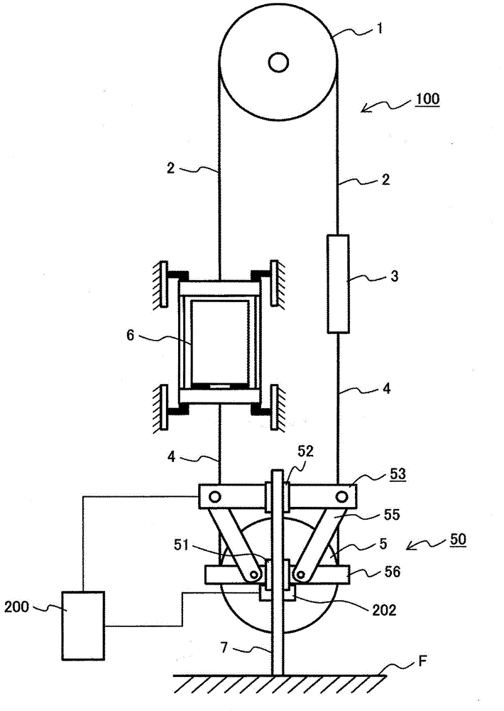
[0064] A first embodiment of the present invention will be described below. figure 1 It is a schematic diagram which shows the whole structure of the elevator apparatus concerning the 1st Example of this invention.

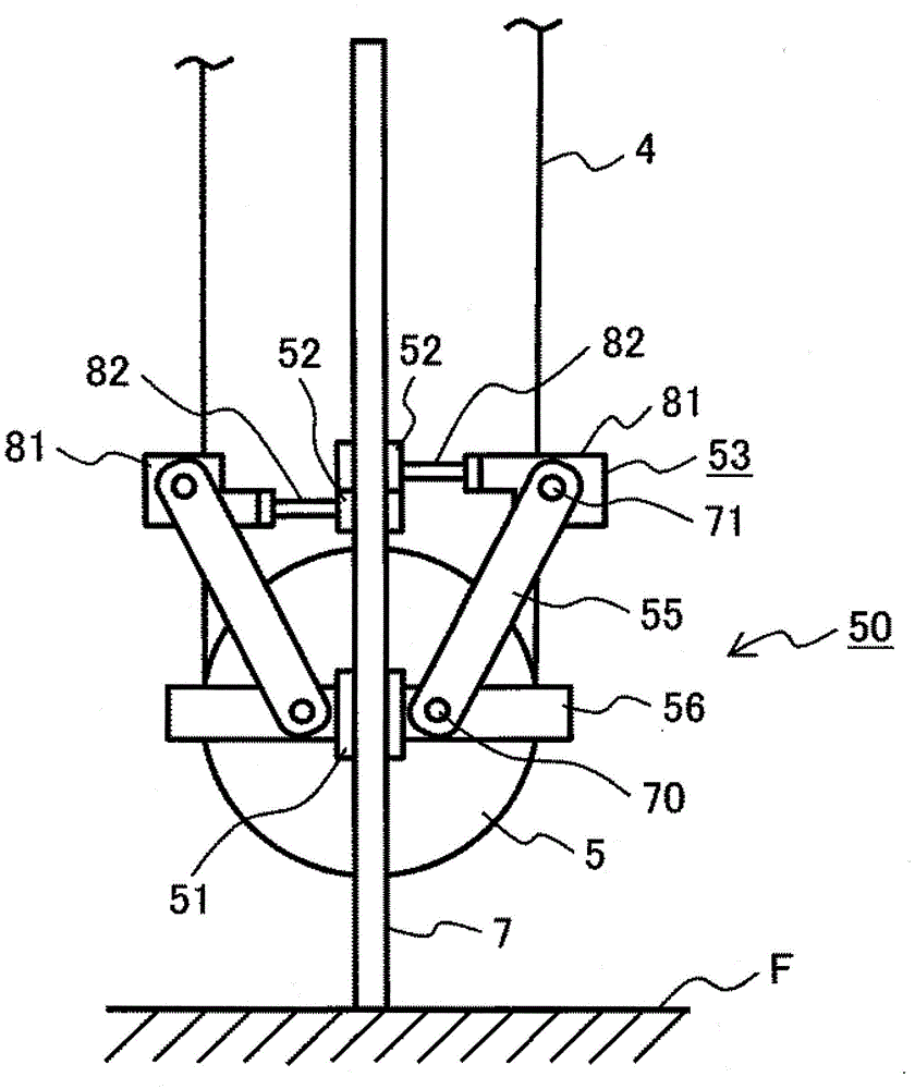
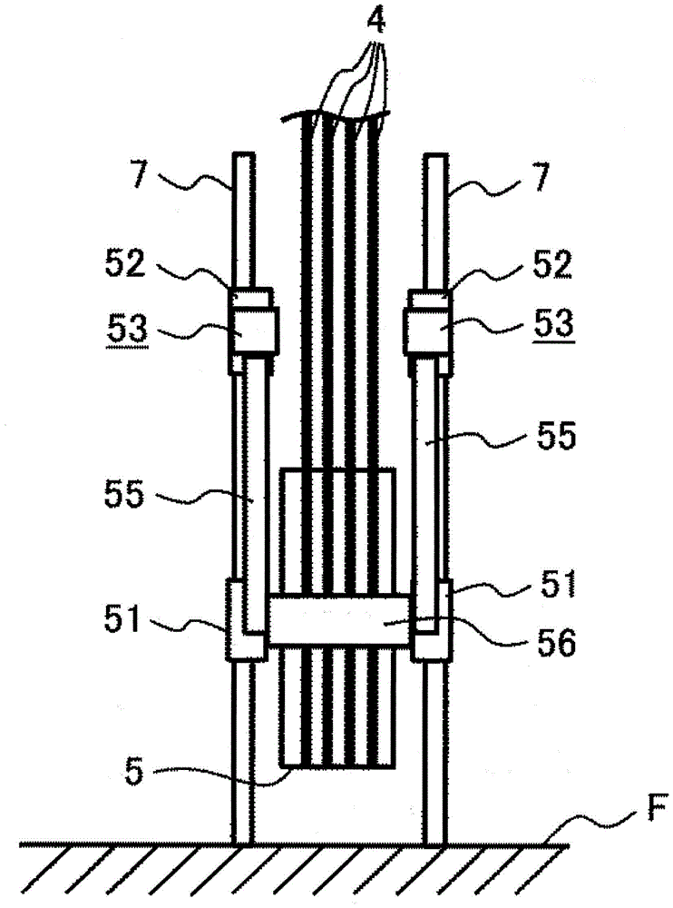
[0065] Such as figure 1As shown, in the elevator equipment 100, the elevator car 6 and the counterweight 3 are connected to the sheave 1 installed on the output shaft of the unshown hoist via the main rope 2. 50 denotes a compensating pulley device, and the compensating rope 4 for compensating the weight change of the main rope 2 due to the position change of the elevator car 6 is connected to the lower side of the elevator car 6 and the counterweight 3 via the compensating pulley 5 . 51 and 52 indicate guide shoes slidably guided by the guide rail 7, 53 indicates an actuator device, and 56 indicates a compensating pulley frame. 55 denotes a link connecting the actuator device 53 and the compensating pulley frame 56 , 200 denotes an actuator control unit, and 20...

no. 2 example

[0079] Refer to the following Figure 6 to Figure 8 A second embodiment will be described. Figure 6 is a schematic diagram showing the overall structure of the elevator equipment 101 according to the second embodiment of the present invention, Figure 7A is a front view showing the structure of the compensating pulley device in the second embodiment, Figure 7B is a side view showing the structure of the compensating pulley device in the second embodiment, Figure 8 It is a perspective view showing the compensating pulley device in the second embodiment.

[0080] exist Figure 6 to Figure 8 Among them, the auxiliary pulley 91 is rotatably held on the auxiliary pulley frame 92, the compensation rope 4 is erected on the auxiliary pulley 91, and the linear actuator 82 of the actuator device 53 is aligned in the direction perpendicular to the guide rail 7. The auxiliary pulley frame 92 and the auxiliary pulley 91 are driven to change the rope tension acting on the compensatio...


PUM


Abstract

PROBLEM TO BE SOLVED: To solve such the problems that in the conventional elevator having a compensation pulley device, a damping effect of a damper is weakened by an increase in amplitude of a rope due to reduction in elasticity of the rope caused by a longer stroke, and a reduction of natural frequency of the rope, and vertical vibration of the compensation pulley device is increased, which causes an elevator car to vibrate vertically to worsen ride comfort.SOLUTION: An elevator device which has a compensation pulley device used for compensating balance of mass of a main rope by which an elevator car and a balance weight are suspended, depending on positions of the elevator car and the balance weight of the elevator device, is provided with: actuator means that gives the compensation pulley pressing force to a guide rail when the compensation pulley vibrates vertically, and increases friction force between the guide rail and the compensation pulley to enhance damping; and link mechanism means that converts displacement in a horizontal direction by the actuator means to displacement in a vertical direction of the compensation pulley.

Description

technical field [0001] The invention relates to an elevator installation with a compensating pulley arrangement with compensating pulleys and compensating ropes. Background technique [0002] Generally speaking, the elevator equipment consists of a sheave installed on the output shaft of the winch, a main rope wound on the sheave, an elevator car suspended by the main rope and controlled by the speed of the hoist, and a hoist suspended on the main A counterweight on the sling and having a mass equal to that of the elevator car. In the bucket-type elevator equipment described above, the lifting and lowering of the elevator car is controlled, and the actual load on the motor is reduced by keeping the masses on the side of the elevator car and the side of the counterweight in balance. [0003] As the stroke of the elevator becomes longer, the mass ratio occupied by the main rope changes due to the position of the elevator car, resulting in an imbalance and a change in the actu...

Claims


Application Information

Patent Timeline
Patent Type & Authority Patents(China)
IPC IPC(8): B66B11/04B66B7/10
Inventor 野泽勇贵宫田弘市三好宽关谷裕二荒川淳井上真辅
Owner HITACHI LTD
Learn More