

Pipeline dredging and leak detection device
A leak detection and pipeline technology, which is applied in indoor sanitary pipeline installations, water supply installations, pipeline systems, etc., can solve the problems that the pressure is difficult to control and affects the effect of pipeline dredging, etc., and achieves saving investigation time, good adaptability, and strong operability Effect
- Summary
- Abstract
- Description
- Claims
- Application Information
AI Technical Summary
Problems solved by technology
Method used
Image

Examples
Embodiment 1
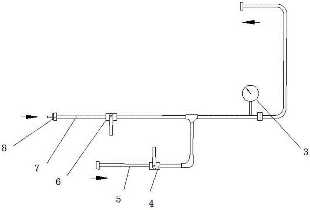
[0037] see figure 1 , the device includes a pipeline equipped with a pressure gauge 3, one end of the pipeline is an air outlet and a water outlet, the other end of the pipeline is connected in parallel with the branch pipe 5, and the other end of the pipeline and the branch pipe 5 are respectively provided with an air inlet valve 6 and a The water inlet valve 4, the other end of the pipeline is communicated with the external inflation device, and the branch pipe 5 is connected with the water source. This device is the most basic device for dredging and leak detection. When dredging the pipeline, connect the hand-push high-pressure gas cylinder at one end of the air inlet or replace the joint with the air pump to inject high-pressure gas, and the gas outlet and water outlet can be directly connected to the part that needs to be dredged. Unclog; when detecting leaks in pipelines, one end of the air outlet and water outlet is connected to the target pipeline, open the water pipe...
Embodiment 2
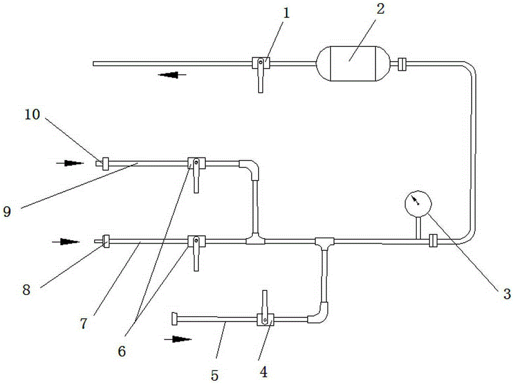
[0039] see figure 2 , this device is to add a gas tank 2 on the pipeline, and install an exhaust and drain valve 1 between the gas tank 2 and the gas outlet, which can store a certain amount of gas. When not in use, close the exhaust and drain valve 1 to input stable Pressure is very effective for dredging the pipelines that are difficult to dredge, and the setting of the gas tank 2 can use the gas in the gas tank 2 to dredge without having to carry the gas cylinder with you. It is suitable for occasions where there is no gas source or no gas cylinder. Convenient; when used as a measuring device, only the gas tank 2 needs to be removed.
Embodiment 3
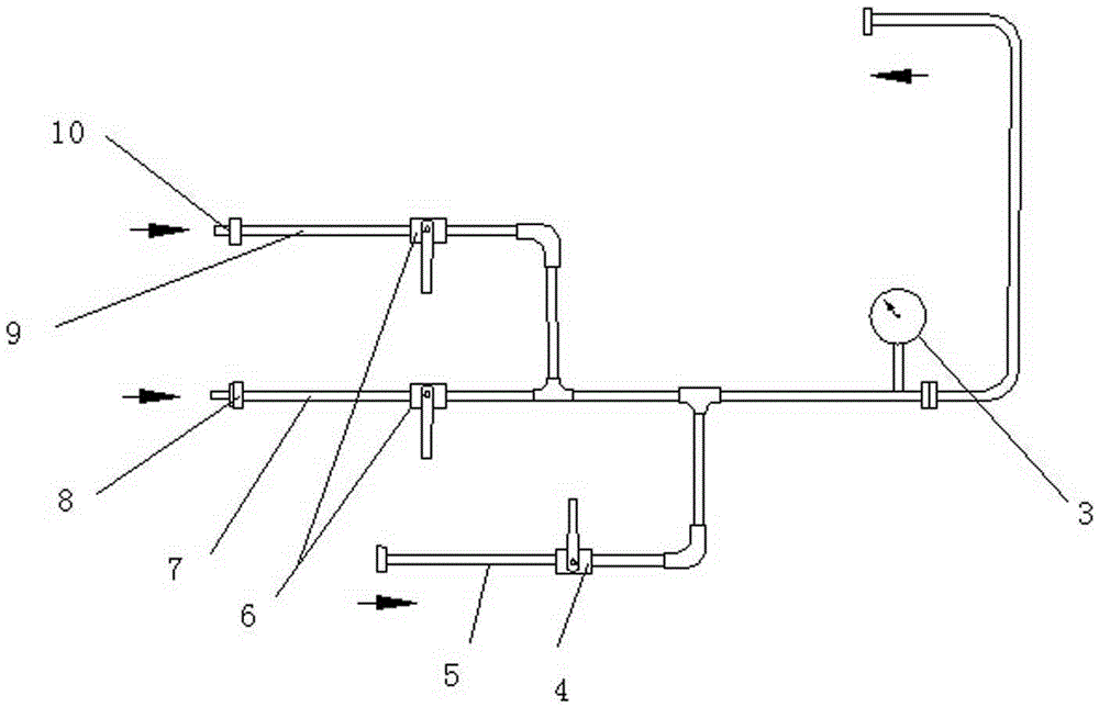
[0041] see image 3 , the other end of the pipeline is divided into a first intake pipe 9 and a second intake pipe 7, and an intake valve 6 is installed on the first intake pipe 9 and the second intake pipe 7, wherein the first The air inlet place of an air intake pipe 9 is connected with the air pump joint 10 that joins with air pump, and the air inlet place of the second branch air inlet pipe 7 is connected with the air cylinder connector 8 that joins with manual air cylinder. The other end of the pipeline is divided into two branches, which are respectively connected with the air pump joint 10 and the air cylinder joint 8, and can be directly connected to the air pump or the air cylinder according to the situation without changing the joints. Both are connected by flexible hoses, which is flexible and convenient.
PUM
 Abstract
Description
Claims
Application Information