LED (light-emitting diode) lamp

A technology for LED lamps and LED strips, applied in the cooling/heating devices, lighting and heating equipment, point light sources, etc. of lighting devices, can solve the problems of insufficient linearity, high energy consumption, low life, etc., and achieve uniform and soft lighting. , The effect of large heat dissipation area and high power

Active Publication Date: 2014-12-24
苏州市琳珂照明科技有限公司
View PDF6 Cites 12 Cited by
  • Summary
  • Abstract
  • Description
  • Claims
  • Application Information

AI Technical Summary

Problems solved by technology

1. High energy consumption, the energy consumption of ordinary fluorescent lamps is equivalent to four times that of LED lamps; 2, fragile, because ordinary fluorescent lamps use glass lamp tubes, glass lamp tubes are easily broken after being hit; 3, not environmentally friendly , because ordinary fluorescent lamps contain mercury, which will cause pollution; 4. Dangerous, ordinary fluorescent lamps use 220V alternating current, such a high voltage can cause harm to the human body; 5. Short life, ultra-low life is frequent maintenance of lamps
[0003] At present, there are also some products that use LED illuminants as light sources, but these lamps have not fundamentally jumped out of the shape of traditional lamps, and still need to set multiple grooves on the ceiling to install the lamps in the grooves, so the installation is inconvenient. After that, the position of the lamp is basically fixed
Moreover, in large places, because the light strips are very long, the linearity of the lamps is not enough after installation, and the light strips are bent, which affects the overall sense of the supermarket. In the pursuit of details and a perfect atmosphere, it is increasingly criticized by many customers with high requirements.

Method used


Image

  • LED (light-emitting diode) lamp
  • LED (light-emitting diode) lamp
  • LED (light-emitting diode) lamp

Examples


Embodiment Construction

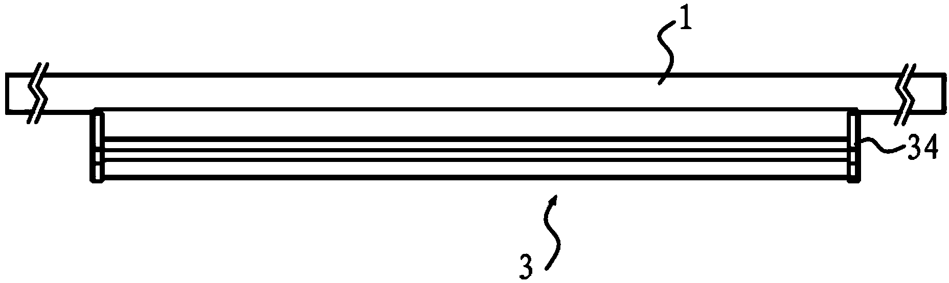
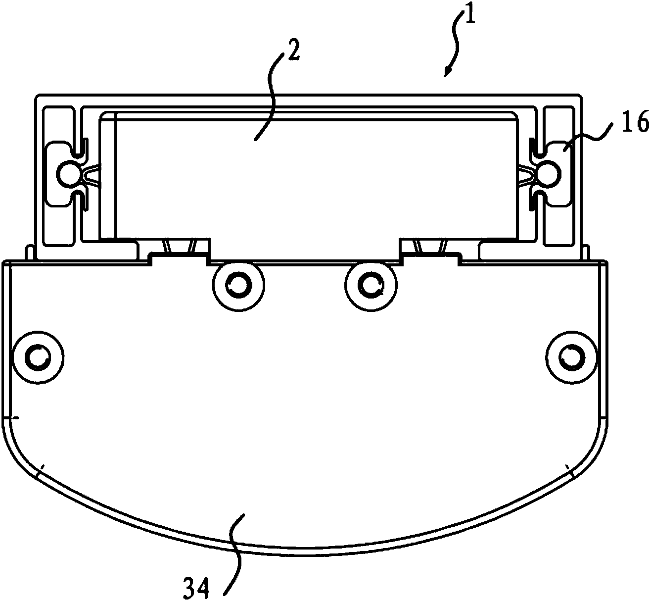
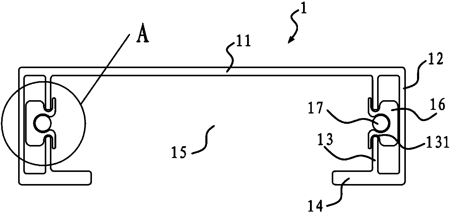
[0038] Attached below Figures 1 to 14 And the specific embodiment will further describe the LED lamp of the present invention.

[0039] As shown in the figure, the LED lamp includes a power supply rail 1 , a power supply unit 2 and a lamp body 3 , and the lamp body 3 includes a reflective bracket 31 , an LED light bar 32 and a lampshade 33 . Wherein, the power supply guide rail 1 is a groove-shaped structure, the power supply unit 2 is arranged in the power supply guide rail 1, one side of the reflective bracket 31 is movably connected with the power supply guide rail 1, the LED light bar 32 is fixed on the reflective bracket 31, and the lampshade 33 is connected with the reflective bracket 31. The other side of the bracket 31 is connected to and covers the top of the LED light bar 32 , and the power supply unit 2 takes power from the power supply rail 1 and transmits it to the LED light bar 32 .

[0040] The LED light bar 32 of the present invention draws power from the pow...


PUM


Abstract

The invention discloses an LED (light-emitting diode) lamp, which comprises a power supply guide rail, a power unit and a lamp body, wherein the lamp body comprises a reflecting bracket, an LED light bar and a lampshade; the power unit is arranged in the power supply guide rail; power is transmitted to the LED light bar after being taken from the power supply guide rail by the power unit. According to the LED lamp, the rail is usually manufactured by a metal section, and the metal section is stretched and formed by virtue of a die when being manufactured, and can be machined to be straight within a certain length range, so that a linearly straight technical effect can be achieved after the whole lamp is mounted; meanwhile, the position of the lamp body can be conveniently shifted along the power supply guide rail without changing the position of the power supply guide rail, so that the LED lamp is more convenient.

Description

technical field [0001] The invention relates to the field of lighting equipment, in particular to an LED lamp. Background technique [0002] At present, lighting fixtures are needed in large places such as supermarkets, shopping malls, and conference venues. At present, ordinary fluorescent lamps are usually used in these places. But ordinary fluorescent lamps have some disadvantages. 1. High energy consumption, the energy consumption of ordinary fluorescent lamps is equivalent to four times that of LED lamps; 2, fragile, because ordinary fluorescent lamps use glass lamp tubes, glass lamp tubes are easily broken after being hit; 3, not environmentally friendly , because ordinary fluorescent lamps contain mercury, which will cause pollution; 4. Dangerous, ordinary fluorescent lamps use 220V alternating current, such a high voltage can cause harm to the human body; 5. Short life, ultra-low life is frequent maintenance of lamps . [0003] At present, there are also some pro...

Claims


Application Information

Patent Timeline
Patent Type & Authority Applications(China)
IPC IPC(8): F21S8/00F21V21/35F21V7/00F21V29/00F21V19/00F21Y101/02
Inventor 鲁周波
Owner 苏州市琳珂照明科技有限公司
Why Eureka
Try Eureka