
A fixed structure of heat absorber tube panel

A technology of heat absorber tube panel and fixed structure is applied in the field of heat absorber tube panel structure and fixed structure. Avoid the effect of bending deformation

Active Publication Date: 2016-03-02
DONGFANG BOILER GROUP OF DONGFANG ELECTRIC CORP
View PDF4 Cites 3 Cited by
  • Summary
  • Abstract
  • Description
  • Claims
  • Application Information

AI Technical Summary

Problems solved by technology

[0003] At present, the independent heating surface tube panel is hung by the upper header or supported by the lower header; the fixing of a single heating tube in the tube panel mostly adopts the common comb-shaped plate structure, and the entire tube panel structure can expand freely in the vertical direction , the heating tube can also expand upwards or downwards as a whole, but a single heating tube inside the tube panel cannot expand freely
[0004] Uneven heat flux density will lead to uneven heat absorption of the heated tubes. In this way, the metal temperature of adjacent tubes may be different, resulting in inconsistent thermal expansion and displacement of a single tube; but the comb-shaped plate connects each tube in the tube panel. The tubes between the upper and lower combs of the tube screen can only expand at the same time, which prevents the free expansion of the tubes with higher temperature, which will cause the tubes between the two combs to bend, deform or even break
Therefore, in the case of uneven heat flux density of the light spot and uneven flow distribution of the working fluid in the tube, the free expansion of individual heated tubes in the tube panel along the vertical direction is restricted, which easily leads to serious deformation and damage of the heated tube, which is not convenient for maintenance. Tube change operation

Method used


Image

  • A fixed structure of heat absorber tube panel
  • A fixed structure of heat absorber tube panel
  • A fixed structure of heat absorber tube panel

Examples


Embodiment 1

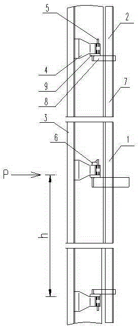
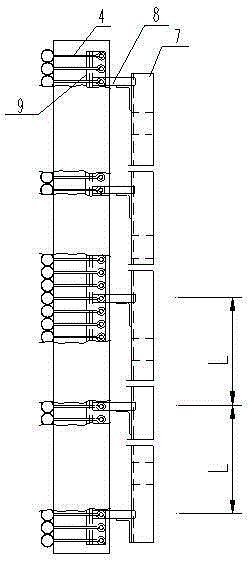
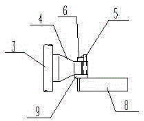
[0023] Such as figure 1 , 2 As shown, a tube panel fixing structure of a heat absorber includes a heated tube 3 forming the tube panel body, a rigid frame 7 supporting the tube panel, a fixed tube clamp set 1 and a sliding tube clamp set 2 . In the specific implementation process, the tube panel is composed of a plurality of light tube heating tubes closely arranged, and tube clamps are set on each heating tube, and the tube clamps at the same horizontal position form a tube clamp group. The fixed tube clamp group is set in the middle of the vertical direction of the tube panel, and the tube panel is fixed by setting blocks; the sliding tube clamp group is not provided with blocks to realize the free expansion of the tube, and the sliding tube clamp group is used to fix the tube panel. The location of the clip group is the zero point of expansion. A row is set up and down along the tube panel at intervals of h according to the height of the tube panel. group) are welded with...


PUM


Abstract

The invention discloses a fixing structure of a tube panel of a heat absorber, which comprises a heat-receiving tube forming a tube panel body, a fixed tube clamp set, a sliding tube clamp set, and a rigid frame supporting the tube panel. At the zero point P, the interval h of the sliding pipe clamp group is set on the upper and lower sides of the fixed pipe clamp group. A fixed tube clamp group is set in the middle of the vertical direction of the tube panel, and a sliding tube clamp group is set up and down according to the height of the tube panel every distance h, which not only ensures the rigidity requirement in the vertical direction of the tube panel, but also ensures that each tube clamp in the tube panel group Welded with separate heating tubes respectively, allowing each heating tube to expand freely upwards or downwards independently with the fixed point in the middle of the vertical direction of the tube panel as the expansion zero point, avoiding the uneven energy flow density of the heating tube due to the spot and the working medium in the tube Bending deformation due to uneven flow; the relatively independent fixed structure of a single tube also makes on-site tube panel maintenance and tube replacement simple and easy.

Description

technical field [0001] The invention relates to a fixing structure of a heat absorber tube panel, in particular to a heat absorber tube panel structure with a fixed and sliding tube clamp group, which can make the heat absorber tube panel expand freely up and down, and belongs to solar heat absorption device technology field. Background technique [0002] In the tower solar thermal power generation system, the solar heat absorber is one of its key equipment. As the core equipment of the tower solar thermal power plant, the heat absorber is used to convert the solar energy with high heat flux density obtained by focusing the heliostat field. It is heat energy of working medium. [0003] At present, the independent heating surface tube panel is hung by the upper header or supported by the lower header; the fixing of a single heating tube in the tube panel mostly adopts the common comb-shaped plate structure, and the entire tube panel structure can expand freely in the vertica...

Claims


Application Information

Patent Timeline
Patent Type & Authority Patents(China)
IPC IPC(8): F24J2/46
CPCY02E10/40
Inventor 臧平伟李有霞奚正稳丁路冉燊铭聂立
Owner DONGFANG BOILER GROUP OF DONGFANG ELECTRIC CORP
Learn More