
Trolley replacement device

A trolley and driving device technology, which is applied to furnaces, furnace types, lighting and heating equipment, etc., can solve problems such as fluctuations in production conditions, large fluctuations in production conditions, and inability to achieve online replacement, and achieve stable production conditions. The effect of improving production efficiency

Active Publication Date: 2017-01-25
SHANDONG PROVINCE METALLURGICAL ENG CO LTD
View PDF7 Cites 0 Cited by
  • Summary
  • Abstract
  • Description
  • Claims
  • Application Information

AI Technical Summary

Problems solved by technology

[0007] 2. Large fluctuations in production conditions
[0008] Sintering or roasting production is a process of continuous air extraction (supply), combustion, and heat exchange. Long-term shutdown will change the production conditions and cause large fluctuations in production conditions.
[0009] 3. Affect product quality
But this must stop the operation of the sintering machine, and online replacement cannot be realized

Method used


Image

  • Trolley replacement device
  • Trolley replacement device
  • Trolley replacement device

Examples


Embodiment 1

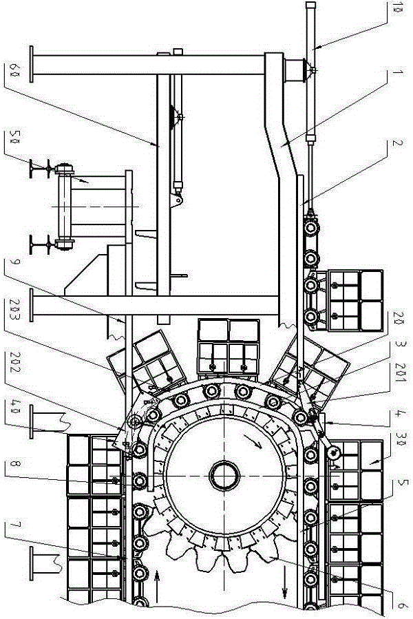
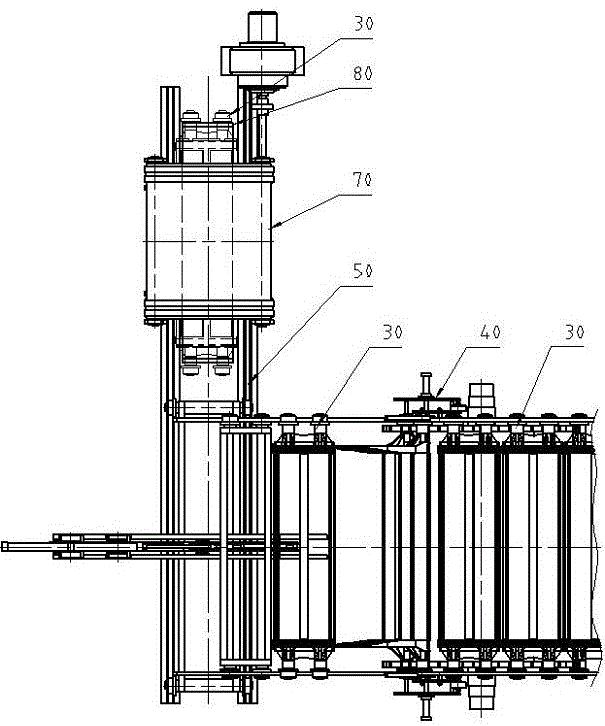
[0066] Example 1, such as Figure 1 to Figure 12 shown.

[0067] The trolley replacement device consists of trolley 30, inner straight rail 5, 8, inner curved rail 3, outer straight rail 4, 7, outer curved rail 20, main drive wheel 6, trolley moving out of rail 9, trolley moving into rail 2 and so on.

[0068] Inner straight rails (5, 8) and inner curved rails (3) form inner guide rails; outer straight rails (4, 7) and outer curved rails (20) form outer guide rails; main drive wheels ( 6), the gear of the main drive wheel (6) is located between the inner guide rail and the outer guide rail;

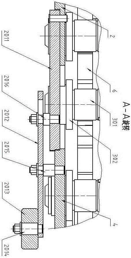
[0069] Outer curved rail 20 is installed on the both sides of main drive wheel 6, is made up of bottom movable outer curved rail 202, middle part fixed outer curved rail 203, top movable outer curved rail 201 etc.

[0070] The lower movable outer curved rail 202 is a partial ring structure, and two round holes are provided at both ends to cooperate with the guide rod 401. The lower mov...

Embodiment 2

[0074] Example 2, Figure 13 shown.

[0075] This embodiment is a change carried out on the basis of Embodiment 1, the difference is:

[0076] 1. Simplify the upper movable outer curved rail 201 in Embodiment 1, cancel the rail II2012, become a single rail and lengthen the rail I2011, and install the weight 2013 directly on the rail I2011.

[0077] 2. At the lower right corner of the upper movable outer curved rail 201, a circular arc step matching the shape of the inner curved rail 3 is provided.

[0078] For the rest, it is the same as Example 1, and reference may be made to this specification and the relevant descriptions of Example 1.


PUM


Abstract

The present invention relates to a trolley replacing device and a trolley replacing method, which belong to the technical field of the replacement of a trolley of a sintering machine or a belt type roasting machine in the metallurgical industry. The trolley replacing device comprises a trolley, an inner straight rail, an inner curved rail, an outer straight rail, an outer curved rail, a main driving wheel, a trolley moving-out rail, and a trolley moving-in rail, wherein the outer curved rail arranged on both sides of the main driving wheel is divided into a lower movable outer curved rail, a middle fixed outer curved rail, and an upper movable outer curved rail; the lower movable outer curved rail is outwardly separated from the middle fixed outer curved rail and a lower outer straight rail on both sides vertical to the operating direction of the trolley, or is connected with the middle fixed outer curved rail and the lower outer straight rail; and one end of the upper movable outer curved rail is connected with one end of the trolley moving-in rail. The present invention enables the sintering machine or the belt type roasting machine to replace the trolley without stalling, and no additional time to replace the trolley is needed, thus increasing the production efficiency; because there are no operations such as stalling the sintering machine or the belt type roasting machine and reducing or stopping the wind, the production condition will not be changed and will be stable relatively; and because of the stable production condition, the production pass rate and the tumbler index will not be reduced.

Description

technical field [0001] The invention relates to a trolley replacement device and method, and belongs to the technical field of trolley replacement for sintering machines and belt roasting machines in the metallurgical industry. Background technique [0002] The grate bars and wheel bearings on the trolley of the sintering machine or belt roasting machine are easily damaged. If the damage is to a certain extent, the faulty trolley must be hoisted out as a whole to replace or repair the grate bars and wheel bearings. enter. [0003] The replacement and installation positions of the existing sintering machine trolley are at the middle tail of the sintering machine and the top of the bellows, and the replacement and installation positions of the belt roaster are at the head of the belt roaster and the top of the bellows. Taking the sintering machine as an example, when the faulty trolley is replaced, the material distribution device stops feeding, the faulty trolley and the tro...

Claims


Application Information

Patent Timeline
Patent Type & Authority Patents(China)
IPC IPC(8): F27B21/08
CPCF27B21/00
Inventor 贠汝平黄东生姚朝胜于忠念
Owner SHANDONG PROVINCE METALLURGICAL ENG CO LTD
Learn More