
Laser alignment device of X-ray machine

A technology of an X-ray machine and an alignment device, applied in the field of X-ray flaw detection, can solve problems such as inaccuracy and achieve the effect of simple structure

Inactive Publication Date: 2014-12-24
BEIJING CHINA POWER LONG YUAN ENVIRONMENTAL PROTECTION TECH
View PDF5 Cites 4 Cited by
  • Summary
  • Abstract
  • Description
  • Claims
  • Application Information

AI Technical Summary

Problems solved by technology

This is only an approximate measurement method, which is extremely inaccurate.

Method used


Image

  • Laser alignment device of X-ray machine

Examples


Embodiment Construction

[0011] The present invention will be described in detail below in conjunction with the accompanying drawings. The description in this part is only exemplary and explanatory, and should not have any limiting effect on the protection scope of the present invention.

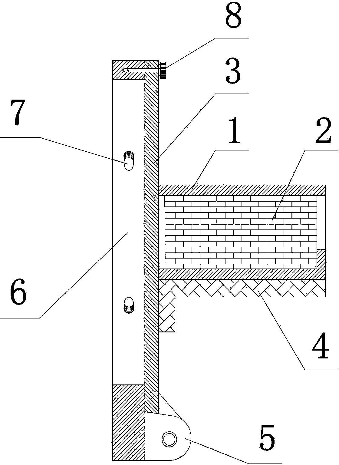
[0012] Such as figure 1 A laser alignment device for an X-ray machine shown includes a window cover 6 of an X-ray machine, a loose-leaf plate 3, a box body 1 and a laser rangefinder 2, and the loose-leaf plate 3 and the window cover 6 are loose-leaf type connected, the box body 1 is fixed on the loose-leaf board 3, and the laser range finder 2 is arranged in the box body 1; the optical line emitted by the X-ray machine and the laser range finder 2 The emitted light lines coincide.

[0013] Corresponding to the light exit of the X-ray machine, the window cover 6 is in the shape of a ring, and an adjusting bolt 7 is arranged in the radial direction. The window cover 6 is sleeved outside the light exit of the X-ray m...


PUM


Abstract

The invention discloses a laser alignment device of an X-ray machine. The laser alignment device comprises a window cover of the X-ray machine, a hinge plate, a box body and a laser distance measuring instrument, wherein the hinge plate is connected with the window cover in a hinge form, the box body is fixed on the hinge plate, and the laser distance measuring instrument is arranged in the box body; a light path emitted by the X-ray machine is overlapped with a light path emitted by the laser distance measuring instrument. The laser distance measuring instrument is additionally arranged at an outlet of the X-ray machine and is connected with the X-ray machine in a hinge form, so that the structure is simple; not only can the distance between the X-ray machine and a target be accurately acquired, but also the laser alignment device is applicable to different X-ray machines and is simple and convenient to install, adjust and operate.

Description

technical field [0001] The invention relates to the technical field of X-ray flaw detection, in particular to a laser alignment device for an X-ray machine. Background technique [0002] The current general X-ray machine alignment device is to add a pull rod similar to the antenna rod type at the X-ray machine window, and its longest length is 600mm. When the tie rod is placed horizontally, the bullseye of the X-ray machine and the center of the film are not on the same line due to the weight of the tie rod itself, so that the center of the film is not on the same line. The focal length greater than 600mm can only be measured visually or by placing a flashlight in the center of the X-ray machine window. For alignment, the actual focal length needs to be measured with a box ruler. This can only be a very approximate measurement method, which is extremely inaccurate. Contents of the invention [0003] Aiming at the deficiencies of the prior art, the present invention propo...

Claims


Application Information

Patent Timeline
Patent Type & Authority Applications(China)
IPC IPC(8): G01N23/04
Inventor 张啸宋绍河
Owner BEIJING CHINA POWER LONG YUAN ENVIRONMENTAL PROTECTION TECH
Learn More