
Scheme for designing circuit used for verifying oscillation starting reliability of crystal oscillator

A technology of circuit design and reliability, which is applied in the field of circuit design schemes to verify the reliability of crystal oscillators. It can solve problems such as time-consuming and laborious, unfavorable testability design, and increased PCB board overhead, so as to achieve the effect of ensuring accuracy.

Inactive Publication Date: 2014-12-24
CHANGSHA JINGJIA MICROELECTRONICS
View PDF5 Cites 1 Cited by
  • Summary
  • Abstract
  • Description
  • Claims
  • Application Information

AI Technical Summary

Problems solved by technology

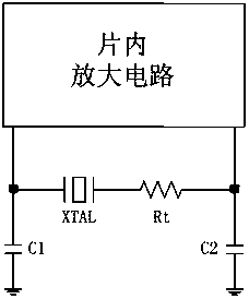
Therefore, after the chip is packaged, it is necessary to test the crystal oscillator. However, when the technicians test and verify the crystal oscillator circuit, they often simply verify whether the crystal oscillator starts to vibrate normally. In-depth research is often rarely done, even if the industry uses an external resistor in series with the crystal, such as figure 1 As shown, there are certain disadvantages in calculating the safety factor: first, the crystal oscillator is a device that is very sensitive to the external environment, adding additional discrete devices such as series resistors can easily cause the crystal oscillator to fail to vibrate; Adding the overhead of additional PCB boards is not conducive to saving costs; third, this verification method is time-consuming and laborious, which is not conducive to the design for testability in large-scale industrial production

Method used


Image

  • Scheme for designing circuit used for verifying oscillation starting reliability of crystal oscillator
  • Scheme for designing circuit used for verifying oscillation starting reliability of crystal oscillator
  • Scheme for designing circuit used for verifying oscillation starting reliability of crystal oscillator

Examples


Embodiment Construction

[0013] The implementation process of a circuit design scheme for verifying the reliability of crystal oscillator start-up disclosed by the invention will be described in detail below in conjunction with the accompanying drawings.

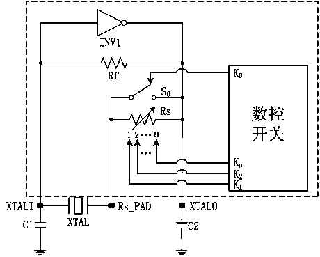
[0014] In the embodiment of the present invention, such as figure 2 As shown, the quartz crystal XTAL, the first capacitor C1, and the second capacitor C2 are all discrete components located outside the chip to form a three-point frequency selection network of the crystal oscillator. The inverting amplifier INV1, the bias resistor Rf, and the conduction switch S 0 , the variable resistor Rs and the digital control switch are integrated in the chip, and are connected to the off-chip through three output pins, which are the first pin XTALI, the second pin Rs_PAD and the third pin XTALO. One end of the first capacitor C1 and the second capacitor C2 are respectively connected to the pins XTALI and XTALO, the other ends of the capacitors are grounded, o...


PUM


Abstract

The invention discloses a scheme for designing a circuit used for verifying the oscillation starting reliability of a crystal oscillator. According to the scheme, a digital-controlled variable resistor is integrated in a traditional crystal oscillator circuit, the resistance value can be controlled flexibly by the resistor through a digital switch, in this way, a critical condition for oscillation starting of the crystal oscillator can be obtained by changing the resistance when the oscillation starting reliability of the crystal oscillator is verified, and then the safety factor of oscillation starting of the crystal oscillator is calculated. By the adoption of the scheme for designing the circuit used for verifying the oscillation starting reliability of the crystal oscillator, cost for testing oscillation starting of the crystal oscillator in the later stage is greatly reduced, time for testing oscillation starting of the crystal oscillator in the later stage is greatly shortened, extra expenditure on PCB testing boards is reduced, and the oscillation starting reliability of the crystal oscillator is verified more accurately.

Description

technical field [0001] The invention is used in the field of integrated circuit design, and in particular relates to a circuit design scheme for verifying the reliability of a crystal oscillator. Background technique [0002] Quartz crystal oscillators are widely used in aviation, aerospace, communications and other fields because they can provide high-precision and high-stability clock sources. As the core part of the clock source, whether the quartz crystal oscillator can start oscillation safely and reliably will directly affect to the normal operation of the entire device. Therefore, after the chip is packaged, the test of the crystal oscillator is an essential work. However, when the technicians test and verify the crystal oscillator circuit, they often simply verify whether the crystal oscillator starts to vibrate normally, which is critical to the reliability of the crystal oscillator. In-depth research is often rarely done, even if the industry uses an external resi...

Claims


Application Information

Patent Timeline
Patent Type & Authority Applications(China)
IPC IPC(8): G01R31/26
Inventor 王志鹏
Owner CHANGSHA JINGJIA MICROELECTRONICS
Learn More