Thermostat for nuclear-magnetic-resonance magnet

A constant temperature device and nuclear magnetic resonance technology, applied in the direction of magnetic resonance measurement, etc., can solve the problems of not specifically teaching the heating mechanism, not specifically teaching the specific structural connection relationship of the constant temperature water tank, water jacket tank, etc., to achieve economical efficiency, simple overall structure, The effect of easy operation

Active Publication Date: 2014-12-24
徐州大彭中药有限公司
View PDF8 Cites 5 Cited by
  • Summary
  • Abstract
  • Description
  • Claims
  • Application Information

AI Technical Summary

Problems solved by technology

[0004] In the published Chinese patent literature, various technical information on the constant temperature of the magnet can be seen, typically such as the "MRI constant temperature water bath controller" recommended by the authorized announcement number CN20140216. The technical effect summarized in line 8, but the patent does not specifically teach the specific structure of the constant temperature water tank (the patent is called the reservoir), the water jacket tank (the patent is called the sample box) and the connection relationship between them, and the patent does not specify Teaching technical content such as the heating mechanism for heating the water bath, so there is no enlightenment for the development of the magnet thermostat with the aforementioned positive significance

Method used


Image

  • Thermostat for nuclear-magnetic-resonance magnet
  • Thermostat for nuclear-magnetic-resonance magnet

Examples


Embodiment

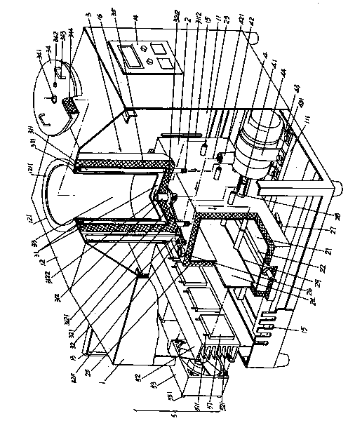
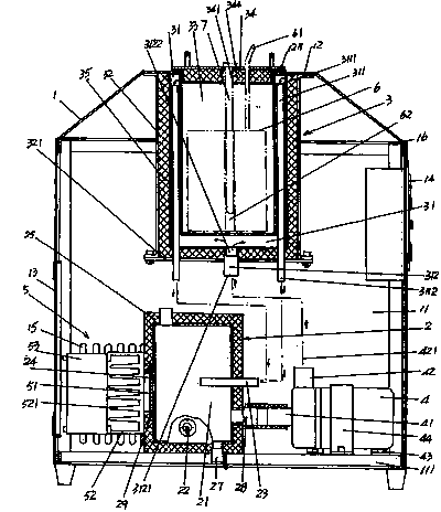
[0023] See figure 1 , a box body 1 is provided, the shape of the lower part of the box body 1 is a rectangle (or a cube), and the shape of the upper part is a quadrangular prism, and the plane of the top constitutes a box top plate 12 . Depend on figure 1 Shown, this box body 1 has a box frame 16, and the aforementioned box body top board 12 and the left box panel, the right box panel, the front box panel and the rear box panel mentioned below are all connected with the box frame 16 as a carrier. Be fixed on the case frame 16. The space in the box body 1 forms a box body cavity 11, and a magnet thermostatic pot connecting hole 121 communicating with the box body cavity 11 is opened on the box body top plate 12, and the magnet thermostatic pot fitting hole 121 is located in the center of the box body top plate 12 Location.

[0024] A liquid medium circulation box 2 is provided, which can also be called a liquid medium constant temperature box, and keeps the liquid medium in ...


PUM


Abstract

The invention discloses a thermostat for a nuclear-magnetic-resonance magnet, and belongs to the technical field of nuclear-magnetic-resonance facilities. The thermostat comprises a tank, a liquid medium circulation tank, a magnet thermostatic tank, a circulating pump and a semiconductor refrigeration mechanism. A magnet-thermostatic-tank fitting hole is formed in a top plate of the tank. The liquid medium circulation tank is arranged in a tank cavity and is fixed with a base of the tank cavity. A heating element and liquid medium return pipes are arranged in a cavity of the liquid medium circulation tank. A heat-exchange conductive plate is arranged in the length direction of the left tank wall of the liquid medium circulation tank. The magnet thermostatic tank is fixed with the top plate of the tank. Liquid medium leading-back pipes are arranged in a jacket cavity of the magnet thermostatic tank. A liquid medium leading-in connector is arranged at the bottom of the jacket cavity. The circulating pump is fixed with the base. A liquid inlet of the circulating pump is communicated with the cavity of the liquid medium circulation tank. A liquid outlet of the circulating pump is connected with the liquid medium leading-in connector. The semiconductor refrigeration mechanism is fixed with the liquid medium circulation tank, and contacts with the heat-exchange conductive plate to enable the magnet to be in an ideal thermostatic state. The thermostat is convenient to operate and produce, small in size and economical.

Description

technical field [0001] The invention belongs to the technical field of nuclear magnetic resonance facilities, and in particular relates to a constant temperature device for a nuclear magnetic resonance magnet, which is used to provide a constant temperature environment for the magnet of a nuclear magnetic resonance instrument. Background technique [0002] The aforementioned nuclear magnetic resonance (English abbreviation: MR) is also called nuclear magnetic resonance imaging technology. Its basic principle is: put the object in a special magnetic field, and use radio frequency pulses to excite the hydrogen nuclei in the object, causing the hydrogen nuclei to resonate and absorb energy. After the radio frequency pulse ends, the hydrogen nucleus emits a radio signal at a specific frequency and releases the absorbed energy, which is received (also called recorded) by an external receiver and processed by an electronic computer to obtain an image. The aforementioned objects i...

Claims


Application Information

Patent Timeline
Patent Type & Authority Applications(China)
IPC IPC(8): G01R33/38
Inventor 李晓南陈国华罗建忠
Owner 徐州大彭中药有限公司
Why Eureka
Try Eureka