Copper wire painting device for horizontal high-speed enamelling machine

An enameling machine and painting technology, applied in the direction of insulating conductors/cables, etc., can solve the problems of too little coating of copper wires, blockage of paint delivery channels, and high hidden dangers of product use, so as to achieve low cost and eliminate instantaneous blockage. Effect

Active Publication Date: 2014-12-24
TONGLING JINGDA REA SPECIAL ENAMELED WIRE
View PDF6 Cites 5 Cited by
  • Summary
  • Abstract
  • Description
  • Claims
  • Application Information

AI Technical Summary

Problems solved by technology

Due to the occasional paint pressure fluctuations when adjusting the paint supply valve of the paint pump, and even foreign matter such as some oxide scales may instantly block the paint conveying channel, often resulting in no paint or less paint in the paint conveying channel
Reflected at the paint outlet, there will be a situation where a certain section of copper wire is coated with too little paint or even cannot be coated smoothly, which will lead to unpainted copper wires or other poor coatings when this sectio...

Method used


Image

  • Copper wire painting device for horizontal high-speed enamelling machine
  • Copper wire painting device for horizontal high-speed enamelling machine
  • Copper wire painting device for horizontal high-speed enamelling machine

Examples


Embodiment Construction

[0028] For ease of understanding, one of the specific implementation structures of the present invention is cited here, and its workflow is described as follows:

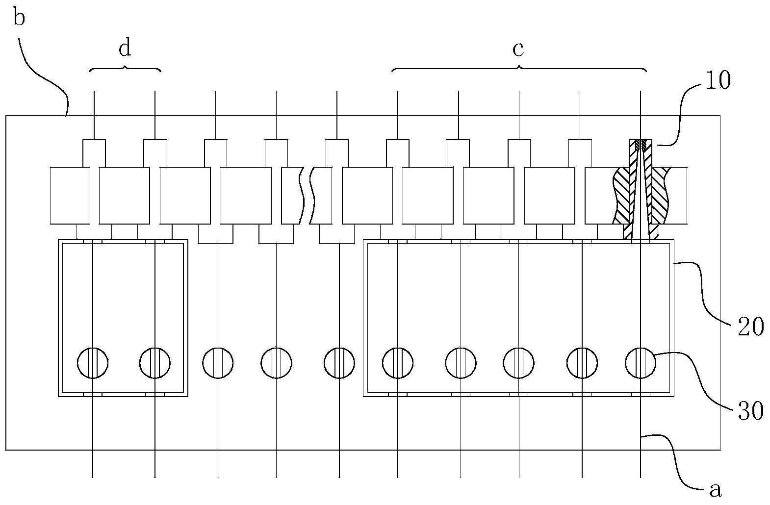
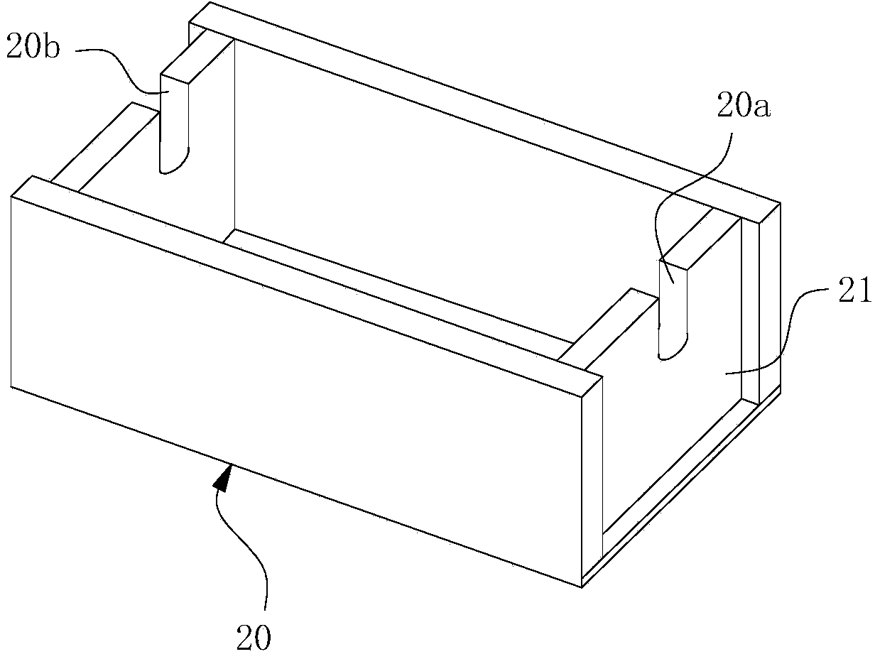
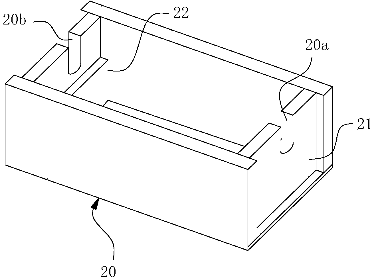
[0029] Figure 5 Among them, the solid line arrow is the traveling direction of the copper wire a, and the dotted line arrow is the paint inlet direction of the paint outlet 30; Figure 2-5 Shown; the layout of the primer painting area c and the surface paint painting area d is as follows figure 1 shown.

[0030] Concrete working structure of the present invention is as Figure 1-5 As shown, it includes a stepped cylindrical paint mold 10 arranged on the support at the enamelling machine b place, the large end of the paint mold 10 is located at the end where the wire inlet is located, and each paint mold 10 is multiple and along its diameter Set to parallel uniform distribution. According to the difference in the number of painting steps required by each paint layer, the number of painting molds 10 used in each ...


PUM

PropertyMeasurementUnit
Lengthaaaaaaaaaa

Abstract

The invention belongs to the field of painting devices of enamelled wires, and particularly relates to a copper wire painting device for a horizontal high-speed enamelling machine. The copper wire painting device is provided with painting molds and a paint supplying device. The painting molds are used for carrying out multi-channel painting on each row wire, and the paint supplying device supplies paint liquid to the painting molds. The painting molds are horizontally arranged in parallel in the axial direction of mold holes in the molds, and containing boxes for containing paint liquid are arranged on wire inlets of the painting molds at the first painting working procedure and the last painting working procedure, each containing box is provided with a wire inlet end and a wire outlet end, copper wires to be painted pass through the wire inlet end and the wire outlet end of each containing box, the arrangement positions of the wire inlet end and the wire outlet end of each containing box are lower than the maximum containing height position of the paint liquid in the corresponding containing box, and the wire inlet end and the wire outlet end of each containing box are coaxial with the wire inlet of the corresponding painting mold. Due to the fact that the containing boxes are used as preparation painting units of the copper wires, painting stability of the enamelled wires at the painting technological position is effectively ensured, and the good film painting and coating effects of the enamelled wires are ensured.

Description

technical field [0001] The invention belongs to the field of enameled wire painting equipment, and in particular relates to a copper wire painting equipment for a horizontal high-speed enamelling machine used for maintaining a good painting effect during enameled wire processing. Background technique [0002] The enameled wire is made by annealing and softening the bare wire, and then going through several times of painting, baking and other processes. In the traditional enameled wire manufacturing process, mold coating is the most widely used coating process. Mold method painting uses a paint mold to form a fixed mold; when performing mold method painting, a paint outlet is arranged before the paint mold, and the paint outlet is located at the travel path of the copper wire to be painted, and the paint liquid is formed by the paint The inside of the box is pumped to the paint outlet through the paint pump. When the copper wire is traveling at high speed, it first passes t...

Claims


Application Information

Patent Timeline
IPC IPC(8): H01B13/16
Inventor 苏保信陈荣郑守国袁平刘盛平艾学举
Owner TONGLING JINGDA REA SPECIAL ENAMELED WIRE
Why Eureka
Try Eureka