Wide-beam antenna of maritime satellite communication terminal

A wide-beam antenna and satellite communication technology, applied in the field of circularly polarized microstrip antenna, wide beam, wide-band, and low profile, can solve the problem of unsatisfactory height-limited use environment, high four-arm helical antenna, and complex antenna structure and other issues, to achieve the effect of low antenna cost, easy product integration, and compact antenna structure

Inactive Publication Date: 2014-12-24
李洪彬 +2
View PDF1 Cites 13 Cited by
  • Summary
  • Abstract
  • Description
  • Claims
  • Application Information

AI Technical Summary

Problems solved by technology

At present, the axial mode helical antenna is widely used in maritime satellite communication. This antenna has the characteristics of high gain and wide frequency bandwidth, but its beam width is narrow, and the half-power beam width is usually about 80 degrees. In order to compensate for the low elevation angle gain, it is usually designed as Active antenna, greatly improving product cost
The quadrifilar helical antenna is a wide-beam antenna. Its half-power beam width can usually reach 150 degrees, but the quadrifilar helical antenna is relatively high. In order to achieve a wider frequency band, the height exceeds 0.8λ (λ is the working wavelength of the antenna). It does not meet the height-restricted use environment, and the structure of this antenna is complex and not easy to produce

Method used


Image

  • Wide-beam antenna of maritime satellite communication terminal
  • Wide-beam antenna of maritime satellite communication terminal
  • Wide-beam antenna of maritime satellite communication terminal

Examples


Embodiment Construction

[0022] The specific embodiments of the present invention will be further described below in conjunction with the accompanying drawings.

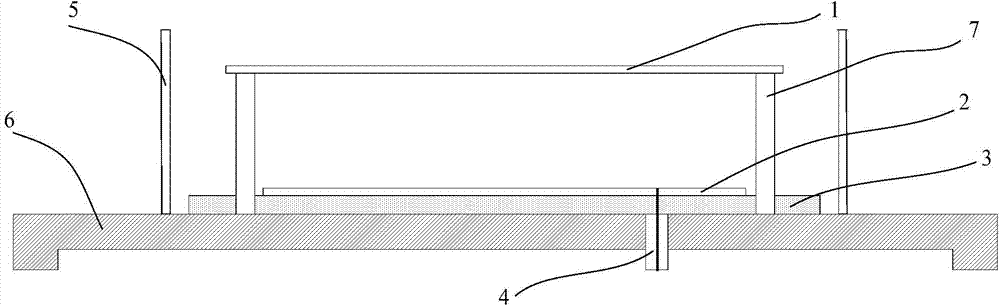
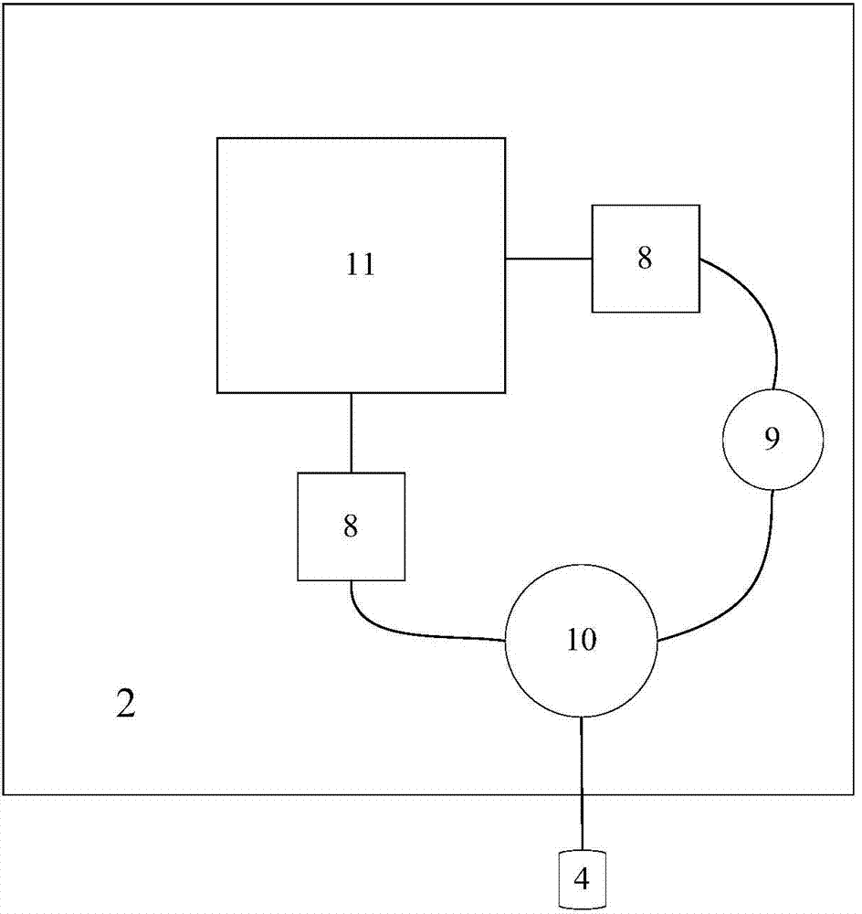
[0023] Such as figure 1 As shown, the antenna device of the present invention structurally includes an upper parasitic patch 1 , a lower circuit 2 , a microwave substrate 3 , a feeding interface 4 , a conductive wall 5 , a reflector 6 and a dielectric stud 7 . Among them, the lower circuit 2 such as figure 2 As shown, it consists of the lower excitation patch 11 , impedance matching branch 8 , phase shifter 9 and power divider 10 . The upper parasitic patch 1 and the lower excitation patch 11 are metal patches with a rotationally symmetrical structure, and the upper parasitic patch 1 is erected directly above the lower excitation patch 11 through a dielectric stud 7 . In order to reduce the size and simplify the structure, the upper parasitic patch 1 and the lower excitation patch 11 are processed into square patches. The microwave subst...


PUM


Abstract

The invention discloses a wide-beam antenna of a maritime satellite communication terminal. The wide-beam antenna comprises an upper parasitic patch, a lower circuit, a microwave substrate, a feed interface, conductive walls, a reflecting sheet and medium studs. The lower surface of the microwave substrate is connected with the reflecting sheet while the upper surface of the same is provided with the lower circuit, and the medium studs penetrate the microwave substrate to be fixed on the reflecting sheet. The upper parasitic patch is set up above the lower circuit through the medium studs, an inner conductor of the feed interface is connected with the lower circuit while an outer conductor of the same is connected with the reflecting sheet, and the conductive walls are arranged on the periphery of the microwave substrate on the reflecting sheet. The lower circuit is composed of a lower parasitic patch, impedance matching branches, a phaser and a power divider, wherein the impedance matching branches are connected between the lower parasitic patch and the power divider as well as between the lower parasitic patch and the phaser. Based on a wide-beam antenna of a stacked structure, the circularly polarized maritime satellite antenna having the advantages of low profile, wide beam and broadband is designed by introduction of the vertical conductive walls, and is simple in structure, easy to produce and low in cost.

Description

technical field [0001] The invention belongs to the technical field of antennas, and relates to a low-profile, wide-beam, wide-band, and circularly polarized microstrip antenna for maritime satellite communication applications. Background technique [0002] In the application of maritime satellite communication, the ground mobile communication terminal antenna is usually required to have the characteristics of wide beam, wide frequency band and circular polarization to meet the communication requirements. At present, the axial mode helical antenna is widely used in maritime satellite communication. This antenna has the characteristics of high gain and wide frequency bandwidth, but its beam width is narrow, and the half-power beam width is usually about 80 degrees. In order to compensate for the low elevation angle gain, it is usually designed as The active antenna greatly increases the product cost. The quadrifilar helical antenna is a wide-beam antenna. Its half-power beam...

Claims


Application Information

Patent Timeline
Patent Type & Authority Applications(China)
IPC IPC(8): H01Q1/38H01Q1/50
Inventor 张生玥李洪彬曹江房少军
Owner 李洪彬
Why Eureka
Try Eureka