Camshaft unit

A technology of camshafts and camshaft adjusters, which is applied to engine components, machines/engines, mechanical equipment, etc., and can solve problems such as manufacturing costs

Inactive Publication Date: 2014-12-24
SCHAEFFLER TECH AG & CO KG
View PDF9 Cites 2 Cited by
  • Summary
  • Abstract
  • Description
  • Claims
  • Application Information

AI Technical Summary

Problems solved by technology

The arrangement is also complex in terms of production due to the large number of components to be installed

Method used


Image

  • Camshaft unit
  • Camshaft unit
  • Camshaft unit

Examples


Embodiment Construction

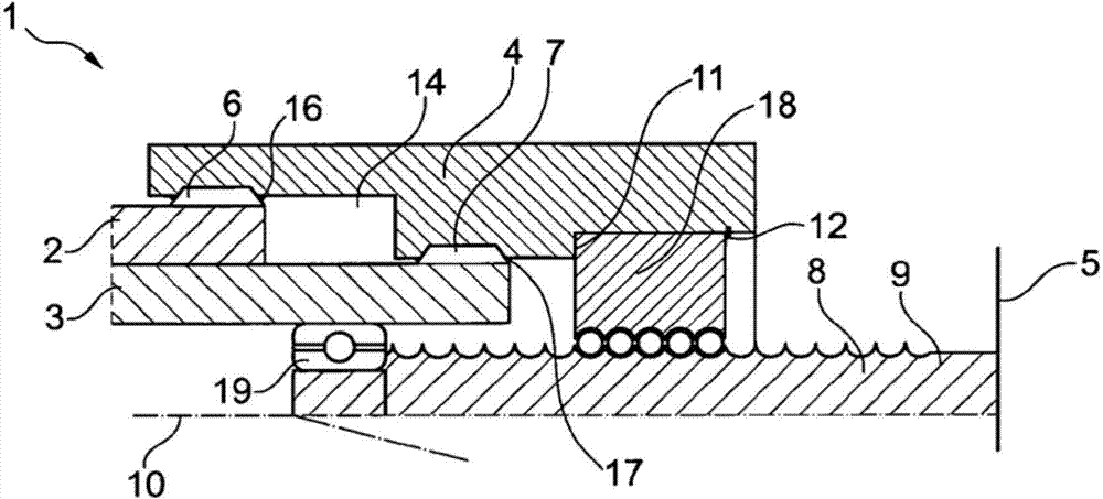
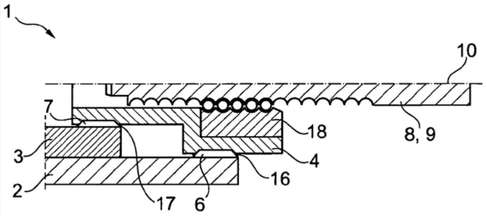
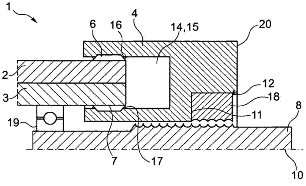
[0026] figure 1 A first camshaft unit 1 is shown, which has a first camshaft 2 , a second camshaft 3 arranged concentrically to the first camshaft 2 , and a connecting element 4 . The connecting element 4 is connected to the first camshaft 2 via a first toothing 16 and to the second camshaft via a second toothing 17 . One of the toothing pairs 6 , 16 and 7 , 17 is designed as a helical toothing and the other pair is designed as a straight toothing.

[0027] The connecting element 4 is designed as a stepped sleeve which has two different inner radii and surrounds the two camshafts 2 , 3 radially on the outside. The inner radius difference corresponds to the ring diameter of the outer camshaft which is now formed by the first camshaft 2 . The two camshafts 2 , 3 extend axially to different extents into the inner cavity 14 of the connecting element 4 . The toothing 16 , 17 of the connecting element 4 meshes with the mating toothing 6 , 7 of the camshaft 2 , 3 . All three comp...


PUM


Abstract

Camshaft unit (1) comprising a first camshaft (2), which is phase-settable with respect to a crankshaft, a second camshaft (3), which is disposed concentric to the first camshaft (2) and is always phase-true to the crankshaft, a camshaft adjuster (5) with which the first camshaft (2) is phase-settable with respect to the crankshaft, a connecting member (4), which is displaceable in the axial direction of the camshafts (2, 3) and has first toothing (16), wherein the first toothing (16) meshes with counter-toothing (6) on the first camshaft (2), and an adjusting drive (9) by means of which a connecting member (4) can be displaced axially, wherein by means of the axial advance, a relative rotation of the first camshaft (2) with respect to the connecting member (4) takes place.

Description

technical field [0001] The invention relates to a camshaft unit having two camshafts arranged concentrically with one another and a camshaft adjuster. Background technique [0002] A camshaft unit with camshafts arranged concentrically with one another, also called a double camshaft, has a first camshaft which extends at least partially as an inner camshaft into a second camshaft as an outer camshaft . Such a camshaft unit for actuating a gas exchange valve of an internal combustion engine is known, for example, from EP 0 582 846 B1 or from US 6,725,817. The camshaft unit has a respective camshaft adjuster for each camshaft, which enables a phase shift relative to the crankshaft. The camshaft adjusters of the camshaft units are each operated hydraulically. On the one hand, such hydraulic drives operate relatively unresponsively and have temperature-dependent control values ​​due to the temperature-dependent viscosity of the oil. Furthermore, larger adjustment angles are ...

Claims


Application Information

Patent Timeline
Patent Type & Authority Applications(China)
IPC IPC(8): F01L1/344
CPCF01L1/34413F01L1/34406F01L2001/34486
Inventor 延斯·舍费尔塞巴斯蒂安·茨瓦尔
Owner SCHAEFFLER TECH AG & CO KG
Why Eureka
Try Eureka