Synthetic aperture radar self-focusing method

A synthetic aperture radar and self-focusing technology, applied in the field of radar, can solve problems such as large amount of computation and low-order phase error in the high-dimensional space search process

Active Publication Date: 2014-12-31
UNIV OF ELECTRONICS SCI & TECH OF CHINA
View PDF3 Cites 16 Cited by
  • Summary
  • Abstract
  • Description
  • Claims
  • Application Information

AI Technical Summary

Problems solved by technology

[0003] The purpose of the present invention is: aiming at the defects in the background technology, research and design a self-focusing algorithm based on the maximum contrast of the image, in order to solve the problem that the existing self-focusing algorithm is only for low-order phase errors, and the phase error estimation without order limit Existing high-dimensional space search process has a large amount of computation

Method used


Image

  • Synthetic aperture radar self-focusing method
  • Synthetic aperture radar self-focusing method
  • Synthetic aperture radar self-focusing method

Examples


Embodiment Construction

[0063] In order to make the object, technical solution and advantages of the present invention clearer, the present invention will be further described in detail below in conjunction with the accompanying drawings and embodiments. It should be understood that the specific embodiments described here are only used to explain the present invention, not to limit the present invention.

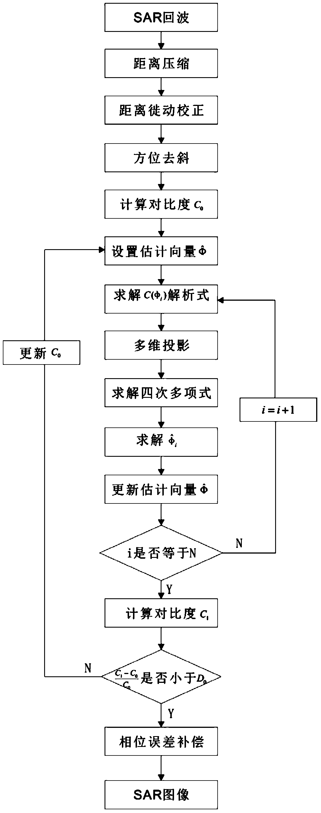
[0064] The present invention mainly adopts the method of simulation experiment to verify, and all steps and conclusions are verified correctly on Matlab2012. like figure 1 As shown, it is a schematic flow chart of the synthetic aperture radar self-focusing method of the present invention. A synthetic aperture radar self-focusing method, comprising the following steps:

[0065] S1. Obtain two-dimensional echo data, use the matched filter method to realize range-to-pulse compression, and point target echo data s after pulse compression 0 (τ,η) is expressed as:

[0066] s ...


PUM


Abstract

The invention discloses a synthetic aperture radar self-focusing method. The synthetic aperture radar self-focusing method specifically comprises the following steps: range pulse compression, range migration correction, azimuth de-ramping, coordinate descent multidimensional phase error estimation, single azimuth unit phase error estimation and multidimensional phase error estimation value output. The synthetic aperture radar self-focusing method disclosed by the invention has the advantages that since a coordinate descent method is used for conducting multidimensional joint estimation of phase errors of each azimuth at each moment and a multidimensional projection method is used for transforming the problem of solving maximum contrast by one-dimension search into the problem of solving a quartic polynomial, the calculation amount is greatly reduced; the estimation of azimuth phase errors by adopting the method disclosed by the invention has the feature of no order limit.

Description

technical field [0001] The invention belongs to the field of radar technology, in particular to a synthetic aperture radar self-focusing method. Background technique [0002] Synthetic Aperture Radar (SAR) is an all-time, all-weather high-resolution microwave remote sensing imaging radar. SAR has played an increasingly important role in the fields of military reconnaissance, topographic mapping, ocean and hydrological observation, environmental and disaster monitoring, resource exploration, and detection of crustal changes. SAR imaging under ideal conditions assumes that the platform moves in a straight line at a constant speed. However, in practice, due to the influence of wind and turbulence, the platform often deviates from the actual trajectory, thereby introducing phase errors and degrading the imaging quality. Therefore, motion compensation is the key technology of SAR high-resolution imaging. At present, SAR motion compensation is mainly divided into two types, one ...

Claims


Application Information

Patent Timeline
Patent Type & Authority Applications(China)
IPC IPC(8): G01S13/90G01S7/02
CPCG01S7/4052G01S13/904G01S13/9019
Inventor 李文超蒲巍杨建宇黄钰林武俊杰李中余杨海光
Owner UNIV OF ELECTRONICS SCI & TECH OF CHINA
Why Eureka
Try Eureka