
A high strength buoyant cable

A floating cable, high-strength technology, applied in the direction of floating cables, insulated cables, power cables, etc., can solve the problems of reduced cable carrying capacity, affecting service life, and large thermal resistance of floating components, so as to improve tension and compression performance and improve adaptability Sexuality, the effect of improving softness

Inactive Publication Date: 2014-12-31
申晓华
View PDF8 Cites 0 Cited by
  • Summary
  • Abstract
  • Description
  • Claims
  • Application Information

AI Technical Summary

Problems solved by technology

Considering the conventional cable design method, the conductor should be in the center. Although the conductor structure is therefore relatively stable, due to the large thermal resistance of the floating element, the overall thermal resistance is bound to be large, resulting in a decrease in the current carrying capacity of the cable, which is not conducive to the large current transmission of the cable.
At the same time, most of the floating cables have poor strength, which affects the service life

Method used


Image

  • A high strength buoyant cable

Examples


Embodiment Construction

[0014] The present invention will be further described below in conjunction with the embodiments with reference to the accompanying drawings.

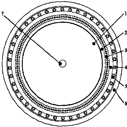
[0015] Such as figure 1 As shown, a high-strength floating cable, a floating element 1 is placed in the center of the cable, and a conductor 3 containing a fiber bundle reinforcement core is arranged outside the floating element 1, and a conductor 3 is provided between the conductor 3 and the floating element 1 A sealing layer 2, the conductor is coated with an inner sheath 4 and an outer sheath 6 in turn, an insulating layer 5 is arranged between the inner sheath 4 and the outer sheath 6, and the insulating layer 5 is formed by an inner insulation Two layers of high-strength steel wires parallel to each other and arranged along the longitudinal direction of the cable are arranged at the central position of the outer sheath wall thickness. Wherein, the conductor 3 is formed by twisting double-layer conductors with the same number and ...


PUM

PropertyMeasurementUnit
thicknessaaaaaaaaaa

Abstract

The invention discloses a high strength buoyant cable. The centre of the cable is provided with a floating element. The outside of the floating element is provided with a conductor which contains a fiber bundle reinforced core therein. A sealing layer is provided between the conductor and the floating element. The outside of the conductor is sequentially clad with an internal sheath and an exterior sheath, wherein an insulating layer is provided between the internal sheath and the exterior sheath, and the insulating layer is a bilayer structure consisting of an internal insulating layer and an exterior insulating layer. The central position, in the wall thickness direction, of the exterior sheath is provided with two high-tensile steel wires that are parallel to each other and arranged along the longitudinal direction of the cable. As compared with the existing art, the inventive cable's conductor employs a stranded conductor with a larger section and meanwhile in part employs an insulated conductor in order to ensure the feasibility and reliability of multipolar power supply, whilst also can greatly enhance the strength and overall performance of the cable by means of adding fiber bundles to optimize the stranded structure design of the conductor as well as providing a tensile means consisting of two parallel high-tensile steel wires at the central position, in the wall thickness direction, of the sheath.

Description

technical field [0001] The invention belongs to the technical field of cables, in particular to a high-strength floating cable. Background technique [0002] High-strength floating cables are important functional components to transmit power and electric energy between ships and surface or underwater working components. The floating component is the key component that determines whether the cable can float on the water surface. Its selection not only determines the floating function index of the cable, but also determines the manufacturing process of the floating cable to the greatest extent. In the past, floating components generally used special wood and hollow metal parts, which were not only expensive but also troublesome to process. Considering the conventional cable design method, the conductor should be in the center. Although the conductor structure is relatively stable, due to the large thermal resistance of the floating element, the overall thermal resistance is b...

Claims


Application Information

Patent Timeline
Patent Type & Authority Applications(China)
IPC IPC(8): H01B7/12H01B7/17H01B7/22H01B7/02H01B9/00
Inventor 申晓华
Owner 申晓华
Learn More