
A dead zone compensation method based on npc three-level svpwm rectifier

A dead-time compensation and rectifier technology, applied in the field of power electronics and power transmission, can solve the problems of reducing the control accuracy of rectifier and inverter, large voltage and current distortion, and output voltage influence, etc., achieving good real-time performance, reducing voltage and Current distortion problem, good compensation effect

Active Publication Date: 2017-01-25
CHINA UNIV OF MINING & TECH
View PDF4 Cites 0 Cited by
  • Summary
  • Abstract
  • Description
  • Claims
  • Application Information

AI Technical Summary

Problems solved by technology

For the dead zone action time, since the potential of each phase on the AC side will fluctuate according to the current direction, it will affect the output voltage and reduce the control accuracy of the rectifier and inverter, so it is necessary to compensate for the dead zone effect
[0003] For dead zone compensation, there are two main current methods: one is hardware compensation, by adding a hardware circuit to compare the actual output voltage with the voltage reference value, directly dynamically adjust the SVPWM output modulation wave, that is, directly change Ta, Tb, Tc The action time is used to compensate the dead zone, but this method requires hardware to detect the current positive and negative online, and the operating cost is relatively high
The second is software compensation. By controlling the dead zone compensation algorithm, there is no need to increase hardware, and the flexibility is strong. However, the selection of compensation amount in the existing software compensation method ignores the conduction voltage drop of power devices such as switch tubes and diodes. The error effect brought by it, resulting in large voltage and current distortion and low compensation accuracy

Method used


Image

  • A dead zone compensation method based on npc three-level svpwm rectifier
  • A dead zone compensation method based on npc three-level svpwm rectifier
  • A dead zone compensation method based on npc three-level svpwm rectifier

Examples


Embodiment Construction

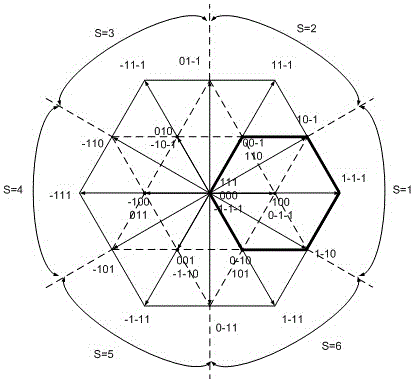
[0045] The specific implementation manners of the present invention will be further described in detail below in conjunction with the accompanying drawings. However, the content disclosed below is the principle of the present invention, and is not limited to this example.

[0046] figure 1 It is a flow chart of the dead zone compensation method of the NPC-based three-level SVPWM rectifier in the present invention.

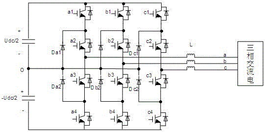
[0047] figure 2 For the main circuit topology diagram based on the NPC three-level SVPWM rectifier, the neutral-point clamped three-phase three-level rectifier includes A, B, and C three-phase bridge arms, and each phase bridge arm consists of 4 switch tubes, 4 Composed of a freewheeling diode and two clamping diodes, O in the figure represents the midpoint; a, b, c represent the AC side input of the three-phase bridge arm; Sa1, Sa2, Sa3, Sa4 represent the four switch tubes of the A phase, Da1 and Da2 represent the 2 clamping diodes of the A phase.

[0048] Th...


PUM


Abstract

The invention discloses a dead-time compensation method for an NPC-based three-level SVPMW (space vector pulse width modulation) rectifier. The method comprises the following steps: firstly, computing the general expression of a dead-time-free reconstitution voltage impulse by not considering tube voltage drop and the general expression of a dead-time reconstitution voltage impulse by considering the tube voltage drop to obtain a general expression of reconstitution voltage impulse compensation amount; then, selecting the general expression of the reconstitution voltage impulse compensation amount, which corresponds to three-phase voltage, according to the directions of all phase current and the timing sequence states of all phase voltages to work out voltage compensation amount; finally, feeding back the worked out voltage compensation amount to a reference voltage vector before being reconstituted, and performing compensation. According to the dead-time compensation method disclosed by the invention, by adopting a novel compensation amount selection method, the compensation amount is computed during a voltage reconstitution process, and compensation participated control is performed on the reference voltage vector; dead time and the tube voltage drop are fully considered, and therefore voltage and current distortion problem generated by the dead-time effect in the NPC-based rectifier is solved, and the system performance is improved.

Description

technical field [0001] The invention relates to a dead zone compensation method of a frequency converter, in particular to a dead zone compensation method based on an NPC three-level SVPWM rectifier, and belongs to the field of power electronics and power transmission. Background technique [0002] In actual rectifier and inverter control, in order to avoid a type of shoot-through short circuit, dead time must be added to prevent power device shoot-through. For the moment of dead zone action, since the potential of each phase on the AC side will fluctuate according to the current direction, it will affect the output voltage and reduce the control accuracy of the rectifier and inverter. Therefore, it is necessary to compensate for the dead zone effect. [0003] For dead zone compensation, there are two main current methods: one is hardware compensation, by adding a hardware circuit to compare the actual output voltage with the voltage reference value, directly dynamically adj...

Claims


Application Information

Patent Timeline
Patent Type & Authority Patents(China)
IPC IPC(8): H02M7/219
Inventor 张辉鱼瑞文王珂张传金史经从
Owner CHINA UNIV OF MINING & TECH
Learn More