Continuous conveying type circular waveguide microwave reactor

A microwave reactor, circular waveguide technology, applied in chemical instruments and methods, chemical/physical/physical-chemical processes, chemical/physical/physical-chemical processes of applying energy, etc., can solve problems such as inability to achieve effects, and achieve reaction efficiency. The effect of increasing and reducing the demand for output power and improving the reaction efficiency

Inactive Publication Date: 2015-01-07
UNIV OF ELECTRONICS SCI & TECH OF CHINA
View PDF8 Cites 5 Cited by
  • Summary
  • Abstract
  • Description
  • Claims
  • Application Information

AI Technical Summary

Problems solved by technology

Due to the shape and the characteristics of the field distribution in the cavity, the above-mentioned existing reactors cannot achieve the best effect

Method used


Image

  • Continuous conveying type circular waveguide microwave reactor
  • Continuous conveying type circular waveguide microwave reactor
  • Continuous conveying type circular waveguide microwave reactor

Examples


Embodiment 1

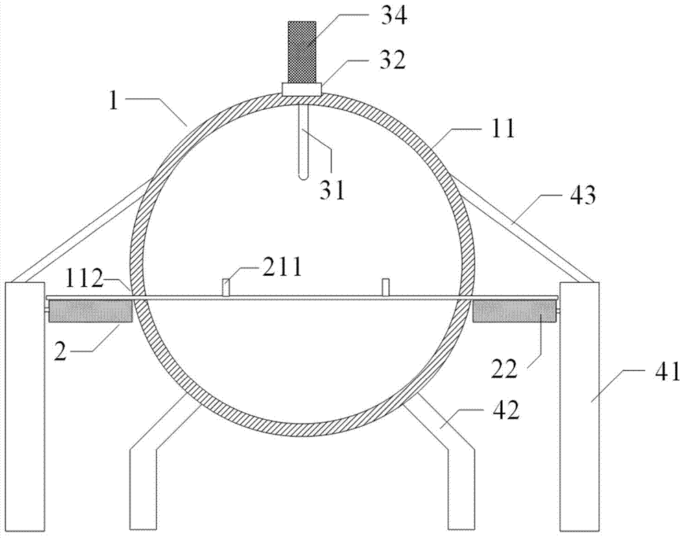
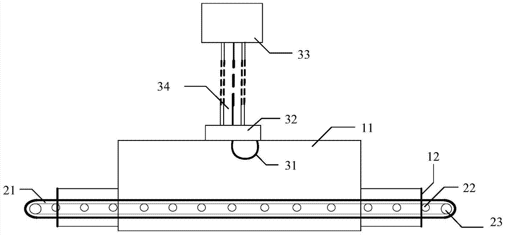
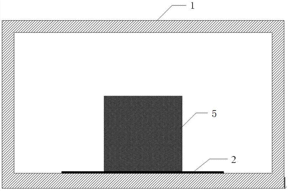
[0024] Embodiment 1: A traveling wave microwave reactor, including a reaction device 1 , a transmission device 2 , a power feeding device 3 , and a support device 4 . It is characterized in that the reaction device 1 is composed of an outer conductor 11 and an anti-leakage device 12, the outer conductor 11 is a cylindrical metal cavity, one end of the metal cavity is provided with a material inlet, and the other end is correspondingly equipped with a material outlet, and the metal cavity is located on the A narrow slit 112 is formed on both sides of the longitudinal axis of the cross section and runs through the whole along the axis. The narrow slit runs through the feed inlet, the side wall of the metal cavity, and the discharge outlet. The width of the slit is not greater than 20mm. Open a feeding circular hole at an appropriate position on the top or bottom of the longitudinal axis of the cross-section of the outer conductor 11; The conveyor belt 21 passes through the slit ...

Embodiment 2

[0031] Embodiment 2: On the basis of Embodiment 1, the length of the outer conductor 11 is changed to 2m, the center of the coupling ring 31 in the feeder 3 is 1m away from the end face of the outer conductor 11, and the radius of the coupling ring 31 is adjusted to 90.89mm.

Embodiment 3

[0032] Embodiment 3: On the basis of Embodiment 1, the cut-off waveguide is replaced by a C14 standard circular waveguide with an inner surface radius of 78.50 mm. The center of circle of the circular waveguide coincides with the center of circle of the outer conductor 11, and two symmetrical slits are opened at the corresponding positions of the side wall of the circular waveguide and the outer conductor 11 so that the conveyor belt 21 can pass through the middle. This example makes it possible to process items such as square cross-sections (or other cross-sections) with a side length of 50-90 mm, which greatly expands the scope of application of the reactor.


PUM


Abstract

The invention discloses a continuous conveying type circular waveguide microwave reactor, belonging to the field of microwave energy application devices. According to the continuous conveying type circular waveguide microwave reactor, a reaction cavity is a cylindrical metal cavity and is divided into two parts along the axial direction so as to mount a conveying belt, and the conveying belt is mounted between the two parts and is driven along the axial direction; support rollers and transmission rollers of the conveying belt are arranged outside the cavity, so that microwave interference in the cavity is avoided; a coupling ring is arranged on the top or bottom of the cavity to achieve the purpose of the invention. Therefore, the continuous conveying type circular waveguide microwave reactor is high in reaction efficiency, reaction speed and reaction uniformity, and energy sources are saved; the continuous conveying type circular waveguide microwave reactor can be applied to large-scale industrial production after being combined with a continuous conveying type production line.

Description

technical field [0001] The invention belongs to the field of microwave energy application devices, in particular to a continuous transmission circular waveguide microwave reactor. Background technique [0002] At present, high-power microwaves have been widely used in heating, medical treatment, drying, coating, environmental protection, auxiliary extraction and other occasions, and good results have been obtained. Now, the application of microwave energy has entered the stage of large-scale industrialization, and the box-type microwave reactor for single treatment is no longer suitable for the needs of industrial production. However, the existing continuous transmission microwave reactors have disadvantages such as low efficiency, uneven field distribution, and slow reaction speed. This requires a high-efficiency, uniform, and fast continuous reactor to be connected with the existing production line to achieve the purpose of reducing energy consumption, improving efficienc...

Claims


Application Information

Patent Timeline
Patent Type & Authority Applications(China)
IPC IPC(8): B01J19/12
CPCB01J19/087B01J19/126B01J2219/00141
Inventor 樊勇程钰间钟熠辰夏支仙
Owner UNIV OF ELECTRONICS SCI & TECH OF CHINA
Why Eureka
Try Eureka