
An industrial pulverizer with noise reduction and temperature reduction function

A kind of pulverizer, industrial technology, applied in the direction of grain processing, etc., can solve the problems of affecting work efficiency, increasing enterprise cost, and can only do secondary crushing, so as to achieve safe and reliable work for workers, improve crushing effect, and avoid manual operation.

Inactive Publication Date: 2016-05-18
中国检验认证集团珠海有限公司
View PDF1 Cites 0 Cited by
  • Summary
  • Abstract
  • Description
  • Claims
  • Application Information

AI Technical Summary

Problems solved by technology

A crushing hammer is set on the disc. During the rotation of the disc, the crushing hammer rotates at high speed and hammers, impacts, shears and grinds the material to make the material crushed. Chinese patent document CN201120206993.X discloses a hammer mill , including the upper casing, the lower casing, the pulley, the rod and the hammer set on the rod, this hammer mill is driven by the pulley to rotate the rod, so that the hammer set on the rod rotates to crush the material , during the crushing process of this kind of hammer mill, because of the large gap between the hammer heads, some chemical raw materials are not completely crushed, and the crushing effect can only be found after the crushing is completed. Some Materials that have not been crushed can only be crushed for the second time, which affects the work efficiency, and because the hammer head rotates at high speed when the crusher is working and needs to beat the materials, it will generate a lot of heat. If the heat cannot be dissipated in time, it will cause High temperature affects the main body of the pulverizer, reducing its service life, thereby increasing the cost of the enterprise. At the same time, high temperature may also affect the properties of some of the crushed materials

Method used


Image

  • An industrial pulverizer with noise reduction and temperature reduction function
  • An industrial pulverizer with noise reduction and temperature reduction function

Examples


Embodiment Construction

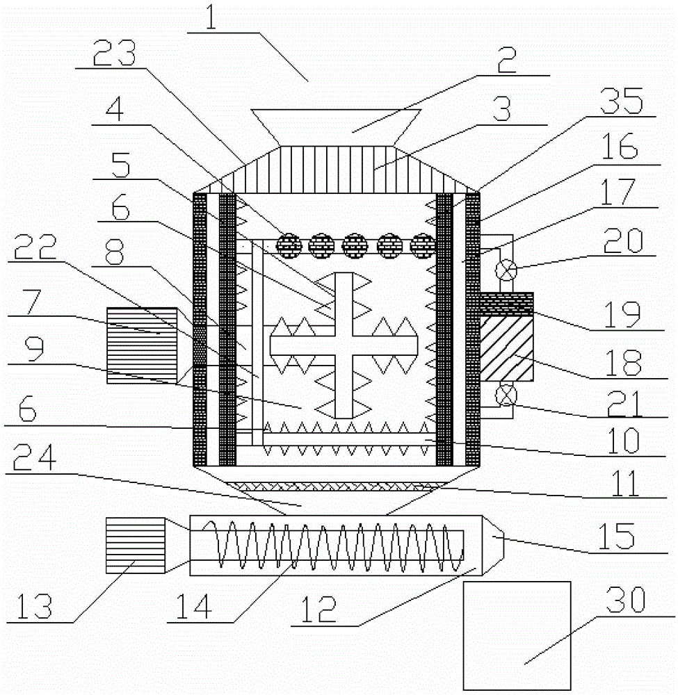
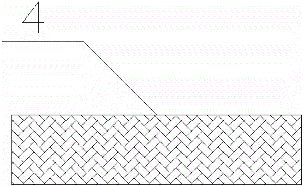
[0037] Such as figure 1 and figure 2As shown, the first embodiment of the present invention is: an industrial pulverizer with noise reduction and cooling function, including a pulverizer body 1 and a storage bin 30, and the pulverizer body 1 includes a feed port 2, a frequency conversion motor 7 , crushing bin 9, stirring wheel 5 and discharge port 15, described feeding port 2 is an inverted trapezoidal structure, is arranged on the top of crushing bin 9, in the feeding channel 23 between feeding port 2 and crushing bin 9 Twelve vertically arranged rectangular deflectors 3 are evenly arranged, and the spacing between each adjacent deflector 3 is 20 to 50 millimeters. The preferred spacing of the present embodiment is 30 millimeters. The deflectors 3. It can ensure that during the process of filling materials, the materials can be evenly entered into the pulverizer body 1 without material congestion. Eight evenly arranged cylindrical squeeze rollers 4 are arranged below the ...


PUM


Abstract

The invention discloses an industrial grinder with noise reduction and temperature reduction functions. The industrial grinder comprises a grinder body and a storage bin, wherein the grinder body comprises a feed port, a variable frequency motor, a grinding bin, a stirring wheel and a discharge port; the feed port is formed above the grinding bin, guide plates are arranged in a feed channel between the feed port and the smashing bin, extrusion rolls are arranged below the guide plates, the stirring wheel and a rotating shaft are arranged in the grinding bin, teeth are arranged on the surfaces of the stirring wheel and the rotating shaft, an inverted trapezoidal discharge hopper is arranged at the bottom of the smashing bin, a filter net is arranged in the discharge hopper, a cooling liquid pipe cavity is further formed and surrounds the outer wall of the grinding bin, and a noise reduction layer is arranged on the outer side of the cooling liquid pipe cavity; a cooling water tank is arranged on the grinder body and communicated with the cooling liquid pipe cavity, and water is circularly supplied by the cooling water tank, so that the grinding bin is cooled. The industrial grinder can thoroughly grind a material, has a good grinding effect and is low in heat productivity and small in noise.

Description

technical field [0001] The invention relates to a pulverizing device, in particular to an industrial pulverizer, which is suitable for processing and pulverizing chemical, pharmaceutical and food raw materials. Background technique [0002] At present, with the rapid development of the machinery industry, a large number of pulverizers are produced and used. In industrial production, putting solid block materials into the pulverizer for crushing and stirring evenly is the most commonly used production process in the pharmaceutical, chemical and food industries. Now Most of the pulverization techniques use hammer mills to beat solid block materials to make them pulverize. Hammer mills generally use a rotating shaft to drive a disc to rotate. A crushing hammer is set on the disc. During the rotation of the disc, the crushing hammer rotates at high speed and hammers, impacts, shears and grinds the material to make the material crushed. Chinese patent document CN201120206993.X di...

Claims


Application Information

Patent Timeline
Patent Type & Authority Patents(China)
IPC IPC(8): B02C21/00B02C23/00B02C23/10
CPCB02C4/32B02C13/282B02C21/00B02C23/00B02C23/02B02C2023/165
Inventor 杜群芳
Owner 中国检验认证集团珠海有限公司
Learn More