
Metal wire production method

A manufacturing method and technology of metal wire, applied in the direction of manufacturing tools, metal processing, metal processing equipment, etc., can solve the problems of uneven incision, numerous processes, high energy consumption, etc., and achieve the effect of smooth incision

Active Publication Date: 2015-01-07
DONGQING TECH
View PDF5 Cites 14 Cited by
  • Summary
  • Abstract
  • Description
  • Claims
  • Application Information

AI Technical Summary

Problems solved by technology

[0002] At present, the production and manufacture of metal wire mainly involves two major difficulties of cutting and straightening the metal wire. When actually cutting the metal wire, most of the methods used are to pull out the metal wire to be cut piece by piece, and cut the knife at intervals. Fixed drop, due to the asynchronous cutting of the cutter, it is easy to cause the incision to be uneven. For the straightening of small-sized wires, the straightening method used usually adopts three sets of straightening rollers arranged crosswise, and a guide The rollers are reasonably arranged, and the first and third groups are double-active, driven by the motor through the special reducer and the direction coupling. When the tube and wire are "bitten" by the rollers, they will move forward with the rotation of the rollers and rotate repeatedly. Bending can be used to straighten the material and reduce the ellipticity of its cross-section. This straightening method not only uses a complex machine structure, many processes, and high energy consumption, it can only process metal wires with a diameter of more than 1mm.

Method used


Image

  • Metal wire production method
  • Metal wire production method

Examples


Embodiment Construction

[0024] Embodiments of the present invention are described in detail below, examples of which are shown in the drawings, wherein the same or similar reference numerals designate the same or similar elements or elements having the same or similar functions throughout. The embodiments described below by referring to the figures are exemplary only for explaining the present invention and should not be construed as limiting the present invention.

[0025] In the description of the present invention, unless otherwise specified and limited, it should be noted that the terms "installation", "connection" and "connection" should be understood in a broad sense, for example, it can be mechanical connection or electrical connection, or two The internal communication of a component can be directly connected or indirectly connected through an intermediary. Those of ordinary skill in the art can understand the specific meanings of the above terms according to specific situations.

[0026] ...


PUM

PropertyMeasurementUnit
angleaaaaaaaaaa

Abstract

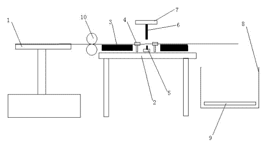
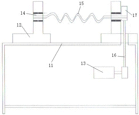
The invention discloses a metal wire production method. The metal wire production method comprises such steps as wire coiled material production, wire coiled material cutting, wire straightening, barreling polishing and packaging warehousing; a wire coiled material is produced through wire drawing equipment and returning equipment, and is put on an active emptying tray of a metal wire cutting device; the active emptying tray is horizontally mounted on the side surface of a frame of the cutting device; two transmission rollers are arranged between the active emptying tray and the frame for emptying assistance; the cutting is performed; after the cutting is finished, the straightening is performed; the barreling and the polishing are performed for straightened metal wires; then, the final checking is performed for the metal wires; and the qualified metal wires are packaged and warehoused. When the metal wires are cut by the metal wire production method, the metal wires are automatically cut without being damaged; meanwhile, when the metal wires are straightened, the straightening precision is largely improved; one motor is needed to provide high-speed rotating power, so that the energy consumption is largely reduced; and the working efficiency is higher.

Description

technical field [0001] The invention relates to the field of metal wire manufacturing, in particular to a metal wire manufacturing method. Background technique [0002] At present, the production and manufacture of metal wire mainly involves two major difficulties of cutting and straightening the metal wire. When actually cutting the metal wire, most of the methods used are to pull out the metal wire to be cut piece by piece, and cut the knife at intervals. Fixed drop, due to the asynchronous cutting of the cutter, it is easy to cause the incision to be uneven. For the straightening of small-sized wires, the straightening method used usually adopts three sets of straightening rollers arranged crosswise, and a guide The rollers are reasonably arranged, and the first and third groups are double-active, driven by the motor through the special reducer and the direction coupling. When the tube and wire are "bitten" by the rollers, they will move forward with the rotation of the r...

Claims


Application Information

Patent Timeline
Patent Type & Authority Applications(China)
IPC IPC(8): B21C37/04B21F11/00B21F23/00B21F1/02B21C51/00
CPCB21C37/047B21C51/00B21F1/026B21F11/00B21F23/00
Inventor 赵烨
Owner DONGQING TECH
Learn More