Forming jig and method for pressing aeroengine mesh parts

A technology for aero-engines and parts, applied in the field of stamping and forming, can solve the problems of difficult control of blank holder force, difficult to achieve, no forming method and experience, etc., and achieves the effect of low processing conditions, broad application prospects and good promotion value.

Active Publication Date: 2016-04-06
AECC AVIATION POWER CO LTD
View PDF5 Cites 0 Cited by
  • Summary
  • Abstract
  • Description
  • Claims
  • Application Information

AI Technical Summary

Problems solved by technology

[0002] The press net of an aero-engine metal mesh part is made of interwoven metal wires with a diameter of φ0.14mm, which requires extremely high formability. If the edge force is too large, it will lead to severe stretching, distortion and deformation of the wire. If the blank holder force is too small during the forming process, the edge of the mesh will wrinkle.
In addition, the traditional stamping die is provided by the equipment to provide blank-holding force, and the forming force is too large, so it is difficult to realize it with the traditional stamping forming processing method, and it is not advisable
However, if the mesh part is formed by knocking with manual fixtures, the force will be uneven, and it is easy to cause serious stretching, distortion or wrinkling in the deformed area of ​​the wire.
There is no domestic manufacturer of this part, and it has been imported from Ukraine for outsourcing. There is no forming method and experience for reference.

Method used


Image

  • Forming jig and method for pressing aeroengine mesh parts
  • Forming jig and method for pressing aeroengine mesh parts
  • Forming jig and method for pressing aeroengine mesh parts

Examples


Embodiment Construction

[0024] Describe the present invention below in conjunction with specific embodiment:

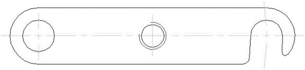
[0025] Refer to attached Figure 7 In this embodiment, an engine mesh part is taken as an example. The material of the part is made of stainless steel wires with a diameter of Φ0.14mm interlaced at 90°. After forming, the height of the part is 11mm, the diameter of the flange is Φ22mm, and the diameter of the cavity is Φ10mm.

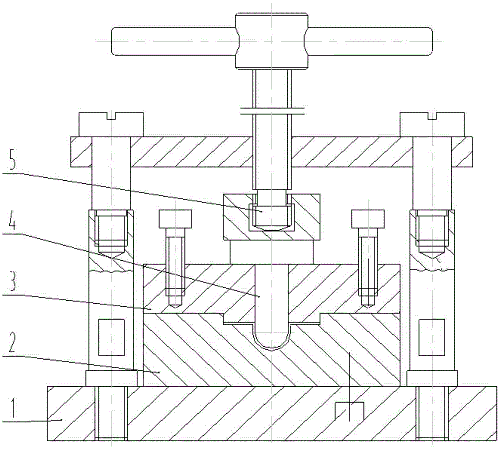
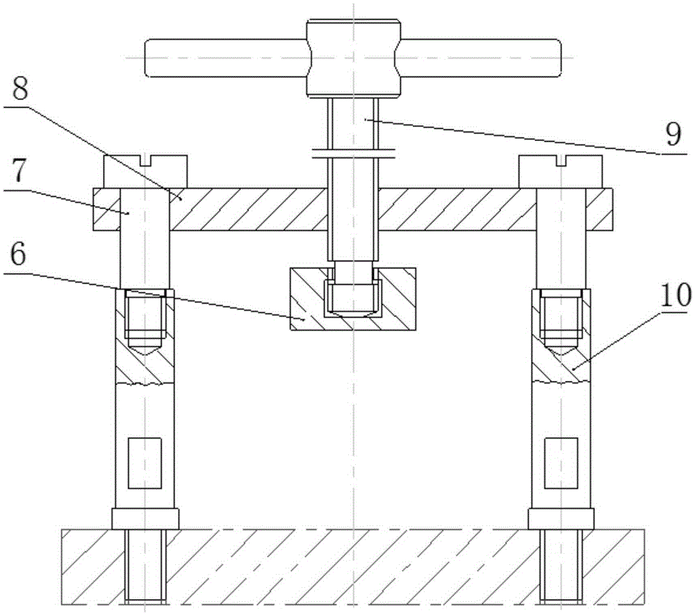
[0026] Forming fixtures used such as figure 1 As shown, it includes a base 1, a lower block 2, an upper block 3, a punch 4 and a force applying mechanism 5. The applying force mechanism includes a pillar 10, a smooth pressing block 6, a pressing screw 7, a rotary pressing plate 8 and a handle 9.

[0027] The base is a supporting part, with a square shape, and a threaded hole is designed on the left and right sides for fixing the pillar.

[0028] The material of the upper and lower blocks is CrWMn, the lower block is fixed on the base, the center of the lower block ...


PUM

PropertyMeasurementUnit
diameteraaaaaaaaaa
diameteraaaaaaaaaa

Abstract

The invention provides an aero-engine netty part press-forming clamp and method. The clamp comprises a base, a lower block, an upper block, a punch and a stress application mechanism, wherein the lower block is fixed on the base, a round counterbore is formed in the center of the lower block, a semispherical pit is formed in the round counterbore, a blank pressing boss is arranged on the lower surface of the upper block, the side face of the blank pressing boss is in clearance fit with the side face of the round counterbore of the lower block, a guiding through hole is further formed in the center of the upper block, the bottom of the punch is spherical, the fit clearance between the punch and the guiding through hole in the upper block is not larger than 0.02 mm, and the step surface of the punch is attached to the upper surface of the upper block. The clamp is easy to operate, safe and reliable when used for machining netty parts, requirements for machining conditions are low, production cost is low, and the shapes and sizes of machined parts meet the requirement of a design drawing.

Description

technical field [0001] The invention relates to the field of stamping and forming, in particular to a forming fixture and method for pressing an aero-engine mesh part. Background technique [0002] The press net of an aero-engine metal mesh part is made of interwoven metal wires with a diameter of φ0.14mm, which requires extremely high formability. If the edge force is too large, the metal wire will be severely stretched and twisted. If the blank holder force is too small during the forming process, the edge of the mesh will wrinkle. In addition, the blank-holding force is provided by the equipment for the traditional stamping die, and the forming force is too large, so it is difficult to realize it with the traditional stamping forming processing method, and it is not advisable. However, if the net-shaped part is formed by knocking with manual fixtures, the force will be uneven, and it is easy to cause serious stretching, distortion or wrinkling in the deformed area of ​​t...

Claims


Application Information

Patent Timeline
Patent Type & Authority Patents(China)
IPC IPC(8): B21D31/04
Inventor 赵海艳陈淳刘军夏国君穆谦王琦穆乐伟任萍
Owner AECC AVIATION POWER CO LTD
Why Eureka
Try Eureka