Equipment for machining ultra-precise end-toothed disc

An end-toothed disc and ultra-precision technology, which is applied in the field of ultra-precision end-toothed disc processing equipment, can solve the problems of difficult processing of the end-toothed disc, high requirements on the manufacturing precision of the end-toothed disc, and high difficulty in turning over, and achieves the effect of ensuring the machining accuracy.

Active Publication Date: 2022-03-04
雄名航空科工(芜湖)股份有限公司
View PDF6 Cites 0 Cited by
  • Summary
  • Abstract
  • Description
  • Claims
  • Application Information

AI Technical Summary

Problems solved by technology

The manufacturing precision of the end tooth disc requires high precision and complicated process
[0003] When the existing end tooth disc is processed, the end tooth on the peripheral side cannot be clamped, so it can only be fixed from the inner hole. Generally, the end tooth disc is placed horizontally on the clamping part, and the straight tooth on the peripheral side is fixed. The teeth or the upper surface are processed, so when the bottom surface is processed, the end tooth plate needs to be turned over. As mentioned above, the end tooth plate is limited by the peripheral teeth. It is difficult to clamp and turn over is more difficult, especially at high Under the high precision requirements, there is an urgent need for an ultra-precision end sprocket processing equipment that can solve the problem that the two sides of the end sprocket are difficult to process

Method used


Image

  • Equipment for machining ultra-precise end-toothed disc
  • Equipment for machining ultra-precise end-toothed disc
  • Equipment for machining ultra-precise end-toothed disc

Examples


Embodiment Construction

[0038] In order to facilitate the understanding of the present invention, the present invention will be described more fully below with reference to the relevant drawings, in which several embodiments of the present invention are shown, but the present invention can be realized in different forms, and is not limited to the text described On the contrary, these embodiments are provided to make the disclosure of the present invention more thorough and comprehensive.

[0039] It should be noted that when an element is said to be "fixed on" another element, it can be directly on the other element or there can be an intervening element, and when an element is said to be "connected" to another element, it can be Directly connected to another element or possibly intervening elements at the same time, the terms "vertical," "horizontal," "left," "right," and similar expressions are used herein for purposes of illustration only.

[0040] Unless otherwise defined, all technical and scien...


PUM


Abstract

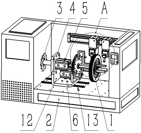
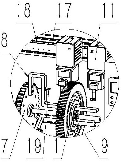
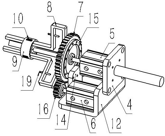
The invention mainly relates to the technical field of machining, in particular to equipment for machining an ultra-precise end-toothed disc. A first linear driving device; the first mounting plate is in transmission connection with the output end of the first linear driving device; a second linear driving device; a first rotation driving device; a turntable; the at least two connecting pieces are fixedly arranged on one side of the turntable; the jacking piece is fixedly arranged at one end of the connecting piece and can extend into the inner hole of the end-toothed disc; the sliding block is connected into the jacking piece in a sliding manner; the two machining devices are connected to the rear side wall of the base in a sliding mode and can machine the two sides of the end-toothed disc, the end-toothed disc is positioned and clamped in the horizontal direction through the jacking pieces and the connecting pieces, and therefore the two sides of the end-toothed disc can be machined at the same time through the subsequent machining devices, and the machining efficiency is improved. The machining precision is guaranteed, and meanwhile the problem that the end-toothed disc needs to be turned over after single-side machining of the end-toothed disc is completed is solved.

Description

technical field [0001] The invention mainly relates to the technical field of mechanical processing, in particular to an ultra-precision end gear processing equipment. Background technique [0002] The end tooth plate is also called the mouse tooth plate or the end tooth plate, which is the core and key component of the mechanical indexing equipment. It can ensure the orderly operation of high-precision indexing of CNC machinery and other equipment. The manufacturing precision of the end tooth disc requires high precision and complicated process. [0003] When the existing end tooth disc is processed, the end tooth on the peripheral side cannot be clamped, so it can only be fixed from the inner hole. Generally, the end tooth disc is placed horizontally on the clamping part, and the straight tooth on the peripheral side is fixed. The teeth or the upper surface are processed, so when the bottom surface is processed, the end tooth plate needs to be turned over. As mentioned ab...

Claims


Application Information

Patent Timeline
Patent Type & Authority Applications(China)
IPC IPC(8): B23F23/06
CPCB23F23/06Y02P70/10
Inventor 王培勇石得林王兵兵
Owner 雄名航空科工(芜湖)股份有限公司
Why Eureka
Try Eureka