Rotary base for workpiece welding and utilization method of rotary base

A technology of rotating the base and workpiece, applied in welding equipment, auxiliary welding equipment, welding/cutting auxiliary equipment, etc., can solve the problems of repeated welding of welds, repeated welding of welds, unstable motor rotation, etc., to reduce work load, ensure work stability, and reduce welding costs

Inactive Publication Date: 2015-01-07
CHENGDU XINGBODA PRECISION MACHINERY
View PDF0 Cites 0 Cited by
  • Summary
  • Abstract
  • Description
  • Claims
  • Application Information

AI Technical Summary

Problems solved by technology

The rotary equipment can make the weld seam on the workpiece be welded in the ideal boat-shaped position or flat welding position, which improves the welding efficiency and reduces the labor intensity; but in the actual operation process, the weld seam often appears when welding the workpiece. Repeated welding or missing welding, the reason is that under the long-term working load, the motor rotation is often unstable, sometimes fast and sometimes slow, whether it is manual welding or mechanical intelligent welding, the solder joints are easy to gather together or the interval is very long A certain distance, which will cause repeated welding or missing welding of the weld seam

Method used


Image

  • Rotary base for workpiece welding and utilization method of rotary base
  • Rotary base for workpiece welding and utilization method of rotary base

Examples


Embodiment 1

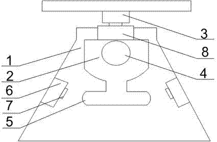
[0019] like Figure 1 to Figure 2 As shown, a workpiece welding rotating base of the present invention and its use method, the workpiece to be welded is fixed on the console 3, the motor 4 is started, the motor 4 drives the mounting seat to rotate, and then the workpiece welding position on the console 3 is changed, which is convenient Quickly weld the workpiece; the bottom of the rotary base 2 is connected with a T-shaped block 5, and the T-shaped block 5 cooperates with the limit blocks 6 at both ends of the support frame 1 to limit the rotation position of the rotary base 2. When the rotary base 2 When rotating clockwise, the T-shaped block 5 collides with the limit block 6 on the left end of the support frame 1. After the travel switch 7 on the limit block 6 contacts the left end of the T-shaped block 5, the travel switch 7 controls the motor 4 to stop rotating. When the slewing base 2 rotates counterclockwise, the T-shaped block 5 collides with the limit block 6 on the ri...

Embodiment 2

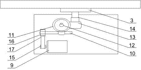
[0021] like figure 2 As shown, on the basis of Embodiment 1, the present embodiment includes a DC motor 9, a first worm 10, a first worm wheel 11 and a support rod 14, and the output end of the DC motor 9 is connected to the first worm 10 , the first worm wheel 11 cooperates with the first worm screw 10, the second worm screw 12 is arranged at the center of the first worm wheel 11, the second worm wheel 13 is installed at the lower end of the support rod 14, the upper end of the support rod 14 is connected with the bottom of the console 3, the second Two worm gears 13 cooperate with the second worm screw 12; A small pulley 15 is installed on the output end of the DC motor 9, and a large pulley 16 is installed on the first worm 10, and the small pulley 15 and the large pulley 16 Connected by belt 17. Considering the requirements of welding speed, the rotary speed of the console 3 is relatively small, so the reduction ratio required is relatively large, and in order to reduce ...


PUM


Abstract

The invention discloses a rotary base for workpiece welding and a utilization method of the rotary base. A deceleration structure comprises a drive device and a deceleration device. According to the arrangement, an operation table is driven to rotate by 360 degrees, and meanwhile, power output of the drive device is stable, so that low-speed stable rotation of the operation table is guaranteed, and welding quality of the workpiece is improved.

Description

technical field [0001] The invention relates to a welding auxiliary tool, in particular to a workpiece welding rotating base and a using method thereof. Background technique [0002] Welding technology has been widely used in light and heavy industries such as aviation and aerospace. The quality of welding directly affects the quality of products and the performance of the whole machine. Therefore, improving welding technology and improving welding quality play an important role in industrial modernization. Among them, improving the level of welding mechanization and automation and realizing the modernization of welding technology and equipment are an important aspect of improving welding quality. Generally speaking, in welding production, there will be When encountering welding displacement and choosing a suitable welding position, in response to this actual need, there are many rotary devices on the market, which can rotate the various welds of the workpiece to be welded t...

Claims


Application Information

Patent Timeline
Patent Type & Authority Applications(China)
IPC IPC(8): B23K37/047
CPCB23K37/047
Inventor 吴光武
Owner CHENGDU XINGBODA PRECISION MACHINERY
Why Eureka
Try Eureka